8. Turbochager
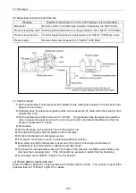
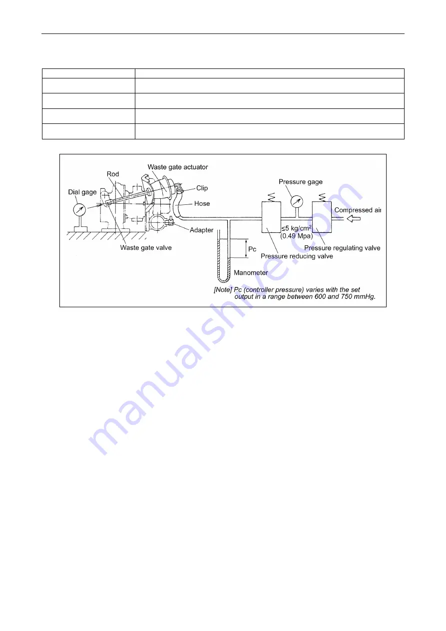
(b) Measuring instruments and devices
Dial gage
Capable of measuring 0 to 10 mm (A flat head type is recommendable.)
Manometer
Mercury column or electrical type (capable of measuring 0 to 1500 mmHg)
Pressure regulating valve Allowing gradual adjustment in a range between 0 and 2 kgf/cm
2
(0.196 Mpa)
Pressure reducing valve
Used for suppressing the air supply pressure at 5 kgf/cm
2
(0.49 Mpa) or less.
Pressure gage
Bourdon tube pressure gage (0 to 10 kgf/cm
2
(0.98 Mpa))
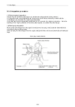
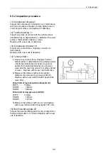
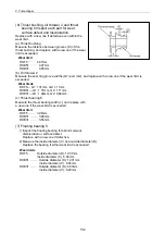
(c) Check method
1) Set the manometer control pressure (Pc) applied to the waste gate actuator to 0 and set the dial
gage to the zero point.
2) Gradually open the pressure regulating valve and measure the Pc value when the actuator rod is
operated by 2 mm.
3) For the hysteresis, let the rod move to 3 mm first. The gradually close the pressure regulating
valve, measure the pressure when the rod is moved to 2mm and obtain the difference from the
pressure measured in b. above.
4) Precautions
Set the dial gage on the extension line of the actuator rod.
The piping and joints shall completely be free from leak.
Fix the turbocharger and dial gage securely.
If an electric manometer is used, it shall have sufficient precision.
Even when an electric manometer is used, use of a mercury column type manometer in
combination is recommended for calibration and daily check.
The speed for increasing/decreasing Pc by means of the pressure regulating valve shall be very
slow near the measuring point. If the mm position is exceeded, restart from the beginning.
Do not apply over 0.49 MPa (5 kgf/cm
2
) to the actuator.
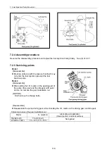
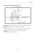
(2) Waste gate actuator leak test
Apply 0.12 Mpa (1.2kgf/cm
2
) to the actuator and hold the state for minute. The actuator is good if the
pressure then is 0.11 Mpa (1.1kgf/cm
2
) or above.
126
Summary of Contents for 3TNV Series
Page 1: ...4TNV106 4TNV106T 4TNV94L 4TNV98 4TNV98T 3TNV82A 3TNV84 T 4TNV84 T 3TNV88 4TNV88 ...
Page 31: ...1 General 1 4 Engine External Views 16 ...
Page 32: ...1 General 1 5 Structural Description 17 ...
Page 156: ...9 Starting Motor 9 1 2 Components 141 ...
Page 157: ...9 Starting Motor 9 1 3 Troubleshooting 142 ...
Page 172: ...9 Starting Motor 9 2 3 Troubleshooting 157 ...
Page 175: ...9 Starting Motor 2 Removal of magnetic switch Remove the M6 bolts 10mm 2 160 ...
Page 185: ...9 Starting Motor 3 Brush 1 Check wear of the brush and the brush spring force 170 ...
Page 194: ...10 Alternator 179 10 1 6 Troubleshooting ...
Page 195: ...11 Electric Wiring 180 11 ELECTRIC WIRING 11 1 Electric Wiring Diagram ...
Page 213: ......


