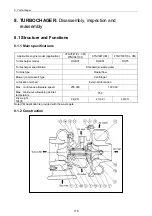

8. Turbochager
8.4.2 Inspection before disassembly
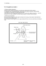
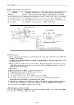
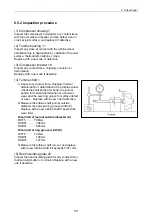
1) Inspect the turbine wheel and compressor impeller for any undesirable contact and the rotor for
smooth rotation.
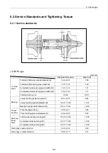
2) Measure the rotor play as described in section 8.3(2.2).
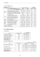
Rotor axial play Wear limit: mm
Rotor radial play Wear limit: mm
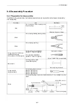
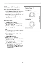
8.4.3 Disassembly
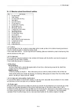
The mounting angles of the turbine housing, bearing housing and compressor housing are determined
according to its mounting state on the engine. Put match marks before starting disassembly.
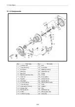
Note: The number after each part is the one described in the structural drawing in 8.1(2).
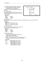
(1) Compressor housing removal
1) Remove flanged hexagon bolt 8 and compressor side keep plate 10.
2) Remove compressor housing 7.
Note:
1) Liquid gasket is applied on the surface of compressor housing 7 where bearing housing 15 is
mounted.
2) When disassembling compressor housing 7, carefully operate so as not to damage the
compressor impeller.
(2) Compressor impeller removal
1) Set a box spanner (10mm) on the turbine side end of the turbine shaft, and remove shaft end clamp
18.
Note: Pay attention to the loosening direction since the shaft end nut has left-handed screw.
2) Remove compressor impeller 18.
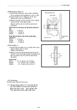
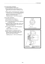
(3) Turbine housing removal
1) Remove hexagon nut 12 and turbine side keep plate 13.
2) Remove turbine housing 11.
(4) Turbine shaft extraction
1) Hold heat insulating plate 20 lightly with a hand, and extract turbine shaft 1.
Note: If the turbine shaft is hard to be extracted, tap the compressor side end of the shaft lightly with
a wooden hammer.
2) Remove heat insulating plate 20.
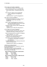
(5) Seal plate removal
1) Use the Torx driver and loosen M3 Torx T-type machine screw 17 for seal plate mounting.
2) Remove seal plate 4.
Note: Liquid gasket has been applied to the seal plate and bearing housing mounting surface.
3) Remove oil thrower 2 from the seal plate.
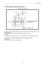
(6) Slide bearing and thrust bushing removal
1) Use the Torx driver and loosen the M3 Torx T-type machine screw for thrust bearing installation.
2) Use the bar (copper) and remove thrust bearing 6 and thrust bushing.
128
Summary of Contents for 3TNV Series
Page 1: ...4TNV106 4TNV106T 4TNV94L 4TNV98 4TNV98T 3TNV82A 3TNV84 T 4TNV84 T 3TNV88 4TNV88 ...
Page 31: ...1 General 1 4 Engine External Views 16 ...
Page 32: ...1 General 1 5 Structural Description 17 ...
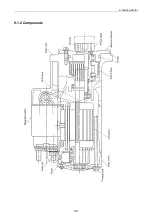
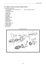
Page 156: ...9 Starting Motor 9 1 2 Components 141 ...
Page 157: ...9 Starting Motor 9 1 3 Troubleshooting 142 ...
Page 172: ...9 Starting Motor 9 2 3 Troubleshooting 157 ...
Page 175: ...9 Starting Motor 2 Removal of magnetic switch Remove the M6 bolts 10mm 2 160 ...
Page 185: ...9 Starting Motor 3 Brush 1 Check wear of the brush and the brush spring force 170 ...
Page 194: ...10 Alternator 179 10 1 6 Troubleshooting ...
Page 195: ...11 Electric Wiring 180 11 ELECTRIC WIRING 11 1 Electric Wiring Diagram ...
Page 213: ......


