
8. Turbochager
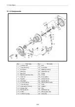
8.6 Reassembly Procedure
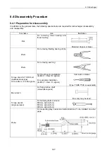
8.6.1 Preparation for reassembly
1) Prepare general tools, special tools, liquid gasket
(Three Bond No.1207) and Locktite No.242
before reassembling the turbocharger.
2) Always replace the following parts with new ones:
Turbine side seal ring 1pc.
Compressor side seal ring(large) 1pc.
Compressor side seal ring(small) 1pc.
M3 machine screws 3pcs.
M3 machine screws 4pcs.
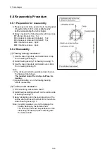
8.6.2 Reassembly
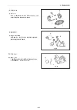
(1) Floating bearing installation
1) Use the snap ring pliers and install inner circlip
16 on bearing housing 15.
2) Install floating bearing 5 in bearing housing 15.
3) Use the snap ring pliers and install outer circlip
16 on bearing housing 15.
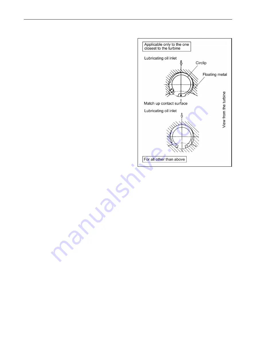
Note:
1) The circlip joint shall be positioned as shown in
the figure at right above.
The rounded side of the circlip shall face the
bearing.
2) Apply lubricating oil on the floating bearing
before reassembly.
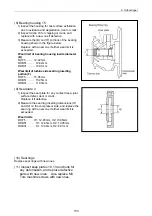
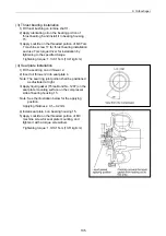
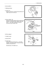
(2) Turbine shaft installation
1) Fit the seal ring onto turbine shaft 1.
2) Install heat insulating plate 20 on the turbine side
of bearing housing 15.
3) Apply lubricating oil on the journal portion of the
turbine shaft and insert the shaft from the turbine
side of bearing housing 15.
Note: Carefully operate so as not to damage the
floating bearing by the turbine shaft.
The seal ring joint shall be positioned on the
lubricating oil inlet side after centering with
the turbine shaft.
134
Summary of Contents for 3TNV Series
Page 1: ...4TNV106 4TNV106T 4TNV94L 4TNV98 4TNV98T 3TNV82A 3TNV84 T 4TNV84 T 3TNV88 4TNV88 ...
Page 31: ...1 General 1 4 Engine External Views 16 ...
Page 32: ...1 General 1 5 Structural Description 17 ...
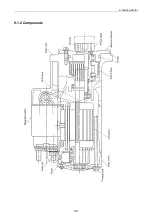
Page 156: ...9 Starting Motor 9 1 2 Components 141 ...
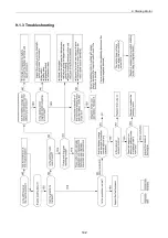
Page 157: ...9 Starting Motor 9 1 3 Troubleshooting 142 ...
Page 172: ...9 Starting Motor 9 2 3 Troubleshooting 157 ...
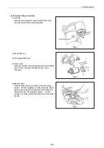
Page 175: ...9 Starting Motor 2 Removal of magnetic switch Remove the M6 bolts 10mm 2 160 ...
Page 185: ...9 Starting Motor 3 Brush 1 Check wear of the brush and the brush spring force 170 ...
Page 194: ...10 Alternator 179 10 1 6 Troubleshooting ...
Page 195: ...11 Electric Wiring 180 11 ELECTRIC WIRING 11 1 Electric Wiring Diagram ...
Page 213: ......


