


10. ALTERNATOR....................................................................................... 176
10.1 The 40A Alternator for 3TNV84 and other models............................................................. 176
10.1.1 Components .......................................................................................................................176
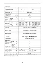
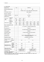
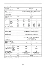
10.1.2 Specifications .....................................................................................................................177
10.1.3 Wiring diagram ...................................................................................................................177
10.1.4 Standard output characteristics ..........................................................................................178
10.1.5 Inspection...........................................................................................................................178
10.2 Troubleshooting ................................................................................................................. 179
11. ELECTRIC WIRING .............................................................................. 180
11.1 Electric Wiring Diagram ..................................................................................................... 180
11.2 PRECAUTION ON ELECTRIC WIRING............................................................................ 181
11.2.1 Alternator ............................................................................................................................181
11.2.2 Starter .................................................................................................................................182
11.2.3 Current limiter .....................................................................................................................183
11.2.4 Section area and resistance of electric wire .......................................................................184
12. SERVICE STANDARDS ....................................................................... 185
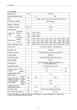
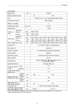
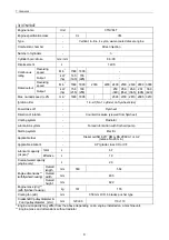
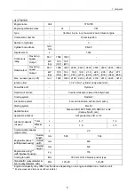
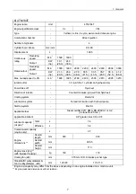
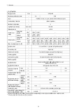
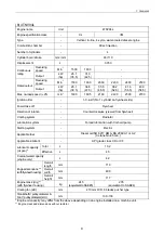
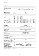
12.1 Engine Tuning.................................................................................................................... 185
12.2 Engine Body ...................................................................................................................... 186
12.2.1 Cylinder head .....................................................................................................................186
12.2.2 Gear train and camshaft.....................................................................................................189
12.2.3 Cylinder block.....................................................................................................................190
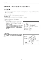
12.3 Lubricating Oil System (Trochoid Pump) ........................................................................... 195
12.3.1 Outside clearance of outer rotor .........................................................................................195
12.3.2 Side clearance of outer rotor ..............................................................................................195
12.3.3 Inside clearance of inner rotor ............................................................................................195
12.3.4 Rotor shaft clearance .........................................................................................................195
13. TIGHTENING TORQUE for BOLTS and NUTS .................................... 196
13.1 Tightening Torques for Main Bolts and Nuts ...................................................................... 196
13.2 Tightening Torques for Standard Bolts and Nuts ............................................................... 197
Summary of Contents for 3TNV Series
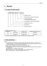
Page 1: ...4TNV106 4TNV106T 4TNV94L 4TNV98 4TNV98T 3TNV82A 3TNV84 T 4TNV84 T 3TNV88 4TNV88 ...
Page 31: ...1 General 1 4 Engine External Views 16 ...
Page 32: ...1 General 1 5 Structural Description 17 ...
Page 156: ...9 Starting Motor 9 1 2 Components 141 ...
Page 157: ...9 Starting Motor 9 1 3 Troubleshooting 142 ...
Page 172: ...9 Starting Motor 9 2 3 Troubleshooting 157 ...
Page 175: ...9 Starting Motor 2 Removal of magnetic switch Remove the M6 bolts 10mm 2 160 ...
Page 185: ...9 Starting Motor 3 Brush 1 Check wear of the brush and the brush spring force 170 ...
Page 194: ...10 Alternator 179 10 1 6 Troubleshooting ...
Page 195: ...11 Electric Wiring 180 11 ELECTRIC WIRING 11 1 Electric Wiring Diagram ...
Page 213: ......


