
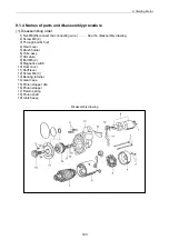

8. Turbochager
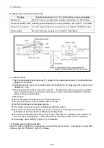
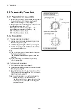
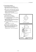
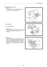
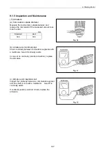
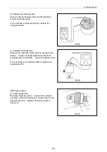
(5) Compressor impeller installation
1) Fit compressor impeller 18 onto turbine shaft 1.
2) Set a box spanner (10 mm) on the turbine side
end of turbine shaft 1, and tighten shaft end nut
19.
Note: Since the shaft end nut has left-handed
screw, pay attention to the tightening
direction.
Tightening torque: 2.0 0.2N-m (20 2kgf-cm)
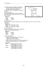
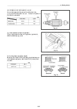
(6) Turbine housing installation
1) Install bearing housing 15 on turbine housing 11
by aligning the match marks put before
disassembly.
Note: In case of part replacement, check the oil
inlet and outlet positions and the exhaust gas
inlet position before reassembly.
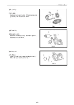
2) Install the turbine side keep plate and tighten M8
hexagon bolt 12.
Tightening torque: 285 10N-m (28 1kgf-cm)
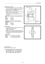
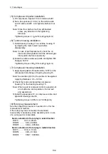
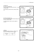
(7) Compressor housing installation
1) Apply liquid gasket (Three Bond No.1207) on the
compressor side flange of bearing housing 15.
Note: See section (4)3) for the portion to be applied.
Applying thickness: 0.1 0.2 mm
2) Check the mark and install the compressor
housing 7 on the bearing housing 15.
Note: When a part is replaced, confirm a position of
an oil entrance and a position of an air exit,
and assemble it.
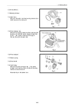
3) Install the keep plate 10 on compressor side, and
tighten M8 hexagon bolt 8.
Tightening torque: 48 N-m (4.7 0.5kgf-cm)
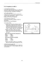
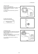
(8) Rotor play measurement
See the inspection procedure in section 8.3.2 for the
measurement method.
If the rotor play does not satisfy the standard,
reassembly is necessary since assembly error or use
of a wrong part is conceivable.
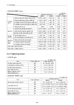
Service standard of rotor play in axial direction
RHF5
0.03 0.06mm
RHB51
0.03 0.06mm
RHB31
0.022 0.053mm
Service standard of rotor play in radial direction
RHF5
0.08 0.13mm
RHB51
0.08 0.13mm
RHB31
0.061 0.093mm
136
Summary of Contents for 3TNV Series
Page 1: ...4TNV106 4TNV106T 4TNV94L 4TNV98 4TNV98T 3TNV82A 3TNV84 T 4TNV84 T 3TNV88 4TNV88 ...
Page 31: ...1 General 1 4 Engine External Views 16 ...
Page 32: ...1 General 1 5 Structural Description 17 ...
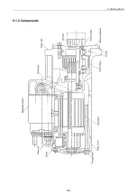
Page 156: ...9 Starting Motor 9 1 2 Components 141 ...
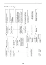
Page 157: ...9 Starting Motor 9 1 3 Troubleshooting 142 ...
Page 172: ...9 Starting Motor 9 2 3 Troubleshooting 157 ...
Page 175: ...9 Starting Motor 2 Removal of magnetic switch Remove the M6 bolts 10mm 2 160 ...
Page 185: ...9 Starting Motor 3 Brush 1 Check wear of the brush and the brush spring force 170 ...
Page 194: ...10 Alternator 179 10 1 6 Troubleshooting ...
Page 195: ...11 Electric Wiring 180 11 ELECTRIC WIRING 11 1 Electric Wiring Diagram ...
Page 213: ......


