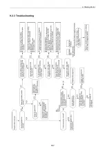
9. Starting Motor
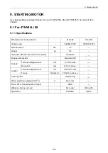
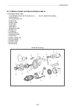
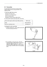
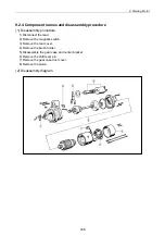
9.1.4 Names of parts and disassembly procedure
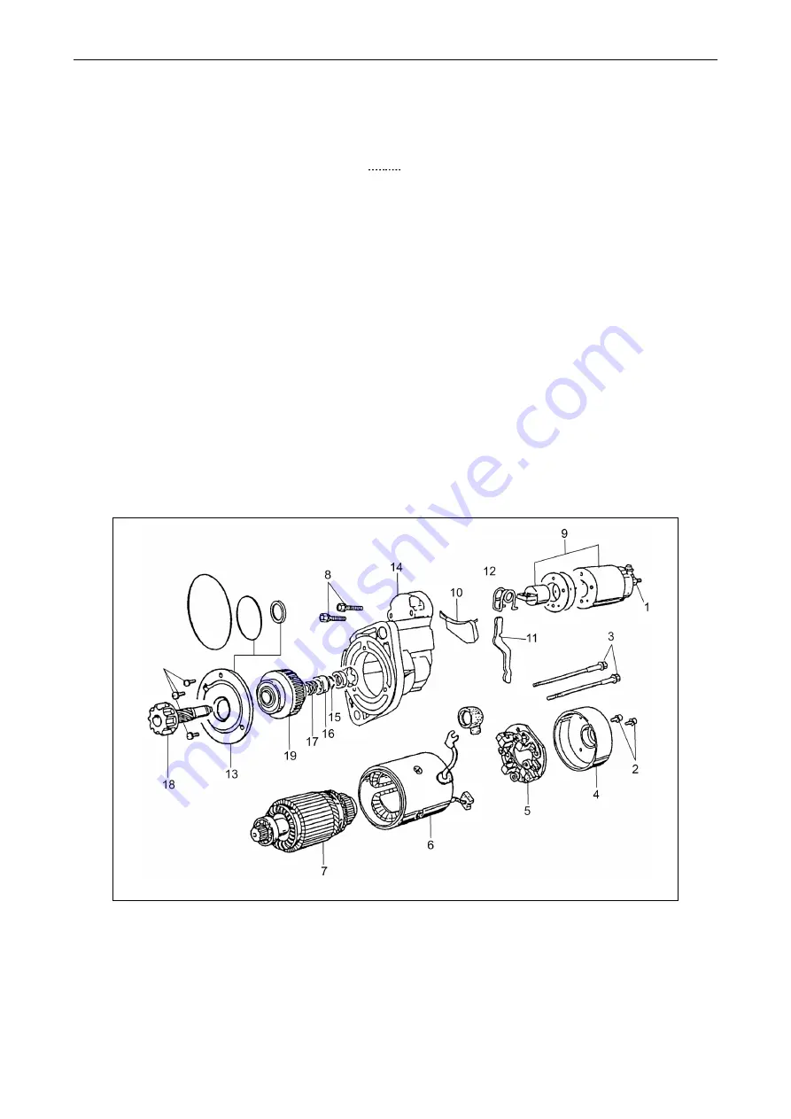
(1) Disassembling order
1) Nut M8 (Disconnect the connecting wire.)
See the disassembly drawing.
2) Screw M4 (2)
3) Through bolt M5 (2)
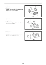
4) Rear cover
5) Brush holder
6) Yoke assy.
7) Armature
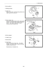
8) Bolt M6 (2)
9) Magnetic switch
10) Dust cover
11) Shift lever
12) Screw M4 (3)
13) Bearing retainer
14) Gear case
15) Pinion stopper clip
16) Pinion stopper
17) Return spring
18) Pinion shaft
19) Clutch assy.
Disassembly drawing
143
Summary of Contents for 3TNV Series
Page 1: ...4TNV106 4TNV106T 4TNV94L 4TNV98 4TNV98T 3TNV82A 3TNV84 T 4TNV84 T 3TNV88 4TNV88 ...
Page 31: ...1 General 1 4 Engine External Views 16 ...
Page 32: ...1 General 1 5 Structural Description 17 ...
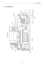
Page 156: ...9 Starting Motor 9 1 2 Components 141 ...
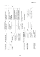
Page 157: ...9 Starting Motor 9 1 3 Troubleshooting 142 ...
Page 172: ...9 Starting Motor 9 2 3 Troubleshooting 157 ...
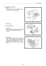
Page 175: ...9 Starting Motor 2 Removal of magnetic switch Remove the M6 bolts 10mm 2 160 ...
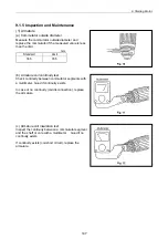
Page 185: ...9 Starting Motor 3 Brush 1 Check wear of the brush and the brush spring force 170 ...
Page 194: ...10 Alternator 179 10 1 6 Troubleshooting ...
Page 195: ...11 Electric Wiring 180 11 ELECTRIC WIRING 11 1 Electric Wiring Diagram ...
Page 213: ......


