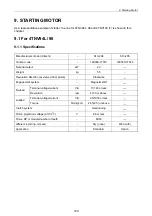
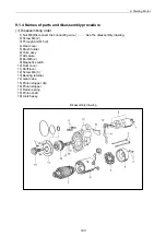
9. Starting Motor
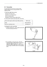
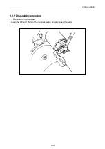
9.1.7 Assembly
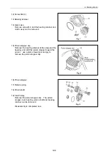
The assembly procedure is the reverse of the
disassembly procedure, but pay attention to the
following points:
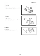
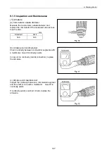
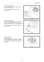
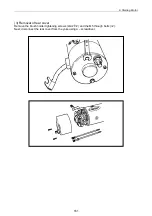
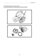
(1) Grease application points
Gears in the gear case
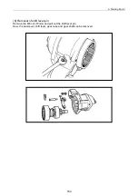
Shift lever operating portion
Pinion sliding portion
Magnetic switch plunger sliding portion
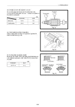
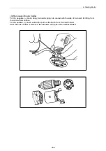
Use the specified grease as below table at all points.
Pinion and magnetic switch plunger sliding portions
NPCFG-6A
Gears MALTEMP
SRL
Shift lever operating portion
ALBANIA No.1
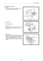
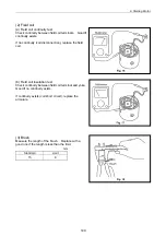
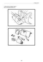
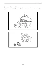
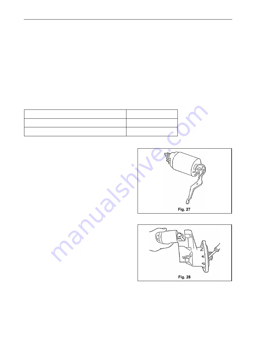
(2) Magnetic switch assembly
1) Install the shift lever on the magnetic switch with
the torsion spring in-between.
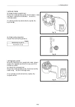
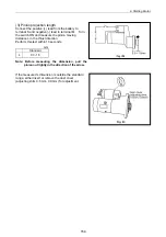
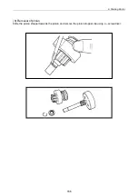
2) For installation on the gear case, install the
magnetic switch with the shift lever on the gear
case after pulling the pinion out. Fix the
magnetic switch by tightening a built-in bolt M6.
Do not forget to install the dust cover (adjusting
shim).
153
Summary of Contents for 3TNV Series
Page 1: ...4TNV106 4TNV106T 4TNV94L 4TNV98 4TNV98T 3TNV82A 3TNV84 T 4TNV84 T 3TNV88 4TNV88 ...
Page 31: ...1 General 1 4 Engine External Views 16 ...
Page 32: ...1 General 1 5 Structural Description 17 ...
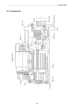
Page 156: ...9 Starting Motor 9 1 2 Components 141 ...
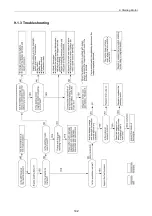
Page 157: ...9 Starting Motor 9 1 3 Troubleshooting 142 ...
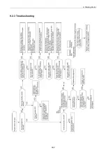
Page 172: ...9 Starting Motor 9 2 3 Troubleshooting 157 ...
Page 175: ...9 Starting Motor 2 Removal of magnetic switch Remove the M6 bolts 10mm 2 160 ...
Page 185: ...9 Starting Motor 3 Brush 1 Check wear of the brush and the brush spring force 170 ...
Page 194: ...10 Alternator 179 10 1 6 Troubleshooting ...
Page 195: ...11 Electric Wiring 180 11 ELECTRIC WIRING 11 1 Electric Wiring Diagram ...
Page 213: ......


