11. Electric Wiring
184
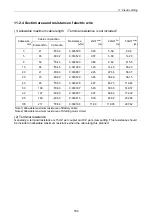
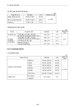
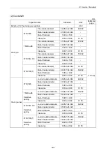
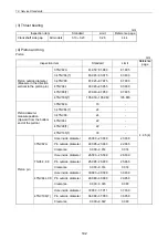
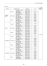
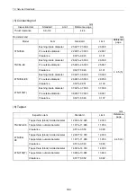
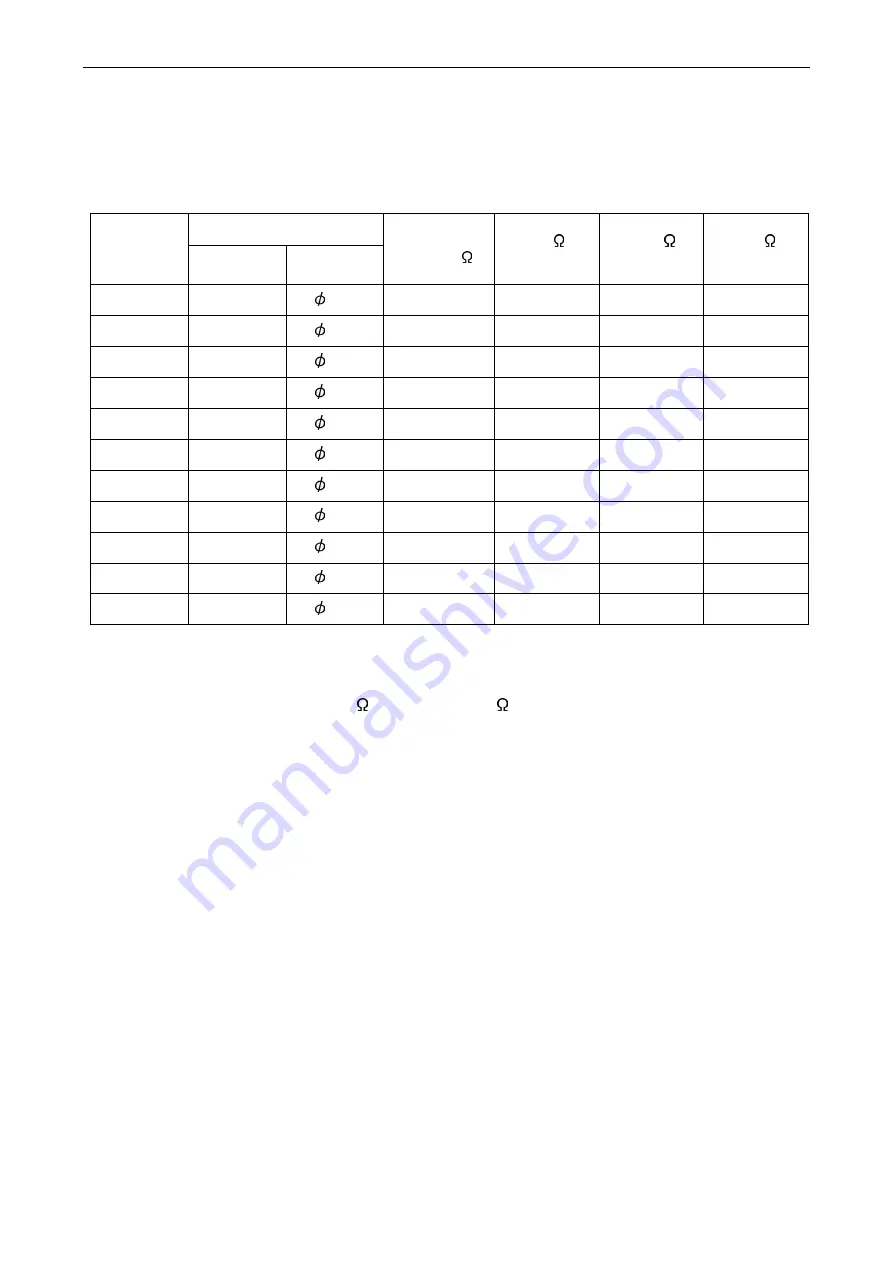
11.2.4 Section area and resistance of electric wire
(1) Allowable maximum cable length
(
Terminal resistance is not included.
)
Cable construction
Cable size
mm
2
Element No. Cable dia.
Resistance
( /m)
2m
Note1
(m)
20m
Ref.
(m)
50m
Note2
(m)
3 41 0.32 0.005590 0.36
3.58
8.94
5 65 0.32 0.003520 0.57
5.68
14.20
8 50 0.45 0.002320 0.86
8.62
21.55
15 84 0.45 0.001380 1.45
14.49 36.23
20 41 0.80 0.000887 2.25
22.55 56.37
30 70 0.80 0.000520 3.85
38.46 96.15
40 85 0.80 0.000428 4.67
46.73 116.82
50 108 0.80 0.000337 5.93
59.35 148.37
60 127 0.80 0.000287 6.97
69.69 174.22
85 169 0.80 0.000215 9.30
93.02 232.56
100 217 0.80 0.000168 11.90 119.05 297.62
Note1) Allowable maximum resistance of Battery cable
Note2) Allowable maximum resistance of Starting motor circuit
(2) Terminal resistance
Generally, a terminal resistance is 15m per coupler and 0 per screw setting. This resistance should
be included in allowable maximum resistance when the cable length is planned.
Summary of Contents for 3TNV Series
Page 1: ...4TNV106 4TNV106T 4TNV94L 4TNV98 4TNV98T 3TNV82A 3TNV84 T 4TNV84 T 3TNV88 4TNV88 ...
Page 31: ...1 General 1 4 Engine External Views 16 ...
Page 32: ...1 General 1 5 Structural Description 17 ...
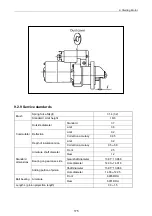
Page 156: ...9 Starting Motor 9 1 2 Components 141 ...
Page 157: ...9 Starting Motor 9 1 3 Troubleshooting 142 ...
Page 172: ...9 Starting Motor 9 2 3 Troubleshooting 157 ...
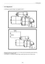
Page 175: ...9 Starting Motor 2 Removal of magnetic switch Remove the M6 bolts 10mm 2 160 ...
Page 185: ...9 Starting Motor 3 Brush 1 Check wear of the brush and the brush spring force 170 ...
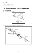
Page 194: ...10 Alternator 179 10 1 6 Troubleshooting ...
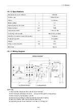
Page 195: ...11 Electric Wiring 180 11 ELECTRIC WIRING 11 1 Electric Wiring Diagram ...
Page 213: ......


