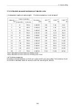
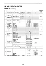
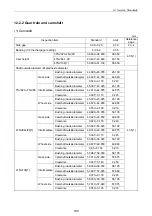
12. Service Standards
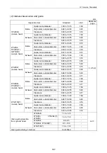
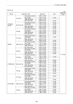
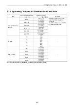
(2) Intake/exhaust valve and guide
mm
Inspection item
Standard
Limit
Reference
page
Guide inside diameter
7.000 7.015 7.08
Valve stem outside diameter
6.945 6.960 6.90
Intake
Clearance 0.040 0.070 0.18
Guide inside diameter
7.000 7.015 7.08
Valve stem outside diameter
6.940 6.955 6.90
3TNV82A
(2-valve head)
Exhaust
Clearance 0.045 0.075 0.18
Guide inside diameter
8.010 8.025 8.10
Valve stem outside diameter
7.955 7.975 7.90
Intake
Clearance 0.035 0.070 0.18
Guide inside diameter
8.015 8.030 8.10
Valve stem outside diameter
7.955 7.960 7.90
4TNV84
3TNV84(T)
3/4TNV88
(2-valve head)
Exhaust
Clearance 0.045 0.075 0.18
Guide inside diameter
6.000 6.015 6.08
Valve stem outside diameter
5.960 5.975 5.90
Intake
Clearance 0.025 0.055 0.15
Guide inside diameter
6.000 6.015 6.08
Valve stem outside diameter
5.945 5.960 5.90
4TNV84T
(4-valve head)
Exhaust
Clearance 0.040 0.070 0.17
Guide inside diameter
7.000 7.015 7.08
Valve stem outside diameter
6.945 6.960 6.90
Intake
Clearance 0.040 0.070 0.17
Guide inside diameter
7.000 7.015 7.08
Valve stem outside diameter
6.940 6.955 6.90
4TNV94L
4TNV98(T)
(4-valve head)
Exhaust
Clearance 0.045 0.075 0.17
Guide inside diameter
7.008 7.020 7.08
Valve stem outside diameter
6.945 6.960 6.92
Intake
Clearance 0.048 0.075 0.16
Guide inside diameter
7.008 7.020 7.08
Valve stem outside diameter
6.960 6.975 6.90
4TNV106(T)
(4-valve head)
Exhaust
Clearance 0.033 0.060 0.18
4.2.5.(2)
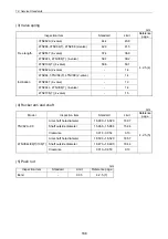
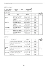
3TNV82A 11.7 12.0 -
4TNV84, 3TNV84(T),
4TNV88
14.7 15.0 -
4TNV84T 8.2 8.5 -
4TNV94L, 4TNV98(T)
9.7 10.0 -
Valve guide projection
from cylinder head
4TNV106(T) 13.4 13.6 -
Valve guide driving-in method
Cold-fitted
-
4.2.7.
187
Summary of Contents for 3TNV Series
Page 1: ...4TNV106 4TNV106T 4TNV94L 4TNV98 4TNV98T 3TNV82A 3TNV84 T 4TNV84 T 3TNV88 4TNV88 ...
Page 31: ...1 General 1 4 Engine External Views 16 ...
Page 32: ...1 General 1 5 Structural Description 17 ...
Page 156: ...9 Starting Motor 9 1 2 Components 141 ...
Page 157: ...9 Starting Motor 9 1 3 Troubleshooting 142 ...
Page 172: ...9 Starting Motor 9 2 3 Troubleshooting 157 ...
Page 175: ...9 Starting Motor 2 Removal of magnetic switch Remove the M6 bolts 10mm 2 160 ...
Page 185: ...9 Starting Motor 3 Brush 1 Check wear of the brush and the brush spring force 170 ...
Page 194: ...10 Alternator 179 10 1 6 Troubleshooting ...
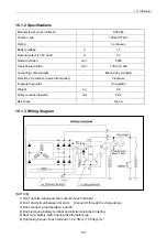
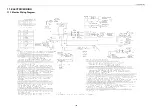
Page 195: ...11 Electric Wiring 180 11 ELECTRIC WIRING 11 1 Electric Wiring Diagram ...
Page 213: ......


