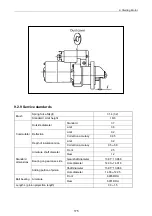
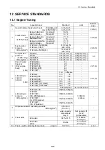
12. Service Standards
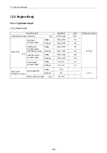
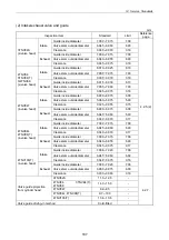
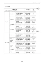
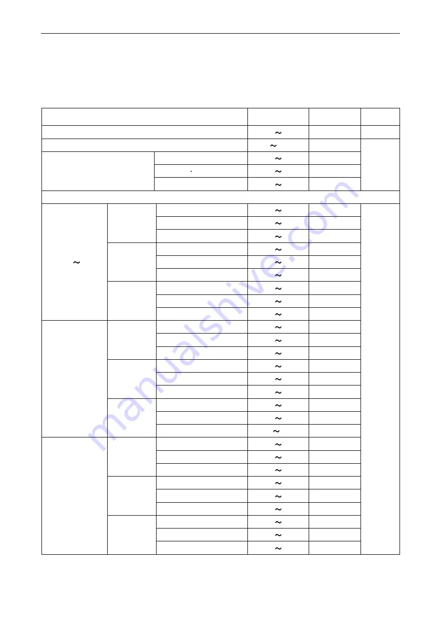
12.2.2 Gear train and camshaft
(1) Camshaft
mm
Inspection item
Standard
Limit
Reference
page
Side gap
0.05 0.20 0.30 4.3.4
Bending (1/2 the dial gage reading)
0 0.02 0.05
3TNV82A-TNV88 38.600 38.800
38.350
4TNV94L 98 43.400 43.600
43.150
Cam height
4TNV106(T) 50.900 51.100
50.650
4.3.5(1)
Shaft outside diameter / Metal inside diameter
Bushing inside diameter
44.990 45.055
45.130
Camshaft outside diameter
44.925 44.950
44.890
Gear side
Clearance 0.040 0.130 0.240
Bushing inside diameter
45.000 45.025
45.100
Camshaft outside diameter
44.910 44.935
44.875
Intermediate
Clearance 0.065 0.115 0.225
Bushing inside diameter
45.000 45.025
45.100
Camshaft outside diameter
44.925 44.950
44.890
TNV82A TNV88
Wheel side
Clearance 0.050 0.100 0.210
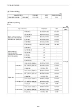
Bushing inside diameter
49.990 50.055
50.130
Camshaft outside diameter
49.925 49.950
49.890
Gear side
Clearance 0.040 0.130 0.240
Bushing inside diameter
50.000 50.025
50.100
Camshaft outside diameter
49.910 49.935
49.875
Intermediate
Clearance 0.065 0.115 0.225
Bushing inside diameter
50.000 50.025
50.100
Camshaft outside diameter
49.925 49.950
49.890
4TNV94L/98(T)
Wheel side
Clearance 0.05 0.100 0.210
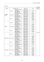
Bushing inside diameter
57.980 58.050
58.105
Camshaft outside diameter
57.910 57.940
57.875
Gear side
Clearance 0.040 0.140 0.250
Bushing inside diameter
58.000 58.030
58.105
Camshaft outside diameter
57.895 57.925
57.860
Intermediate
Clearance 0.075 0.135 0.245
Bushing inside diameter
58.000 58.030
58.105
Camshaft outside diameter
57.910 57.940
57.875
4TNV106(T)
Wheel side
Clearance 0.050 0.120 0.230
4.3.5(1)
189
Summary of Contents for 3TNV Series
Page 1: ...4TNV106 4TNV106T 4TNV94L 4TNV98 4TNV98T 3TNV82A 3TNV84 T 4TNV84 T 3TNV88 4TNV88 ...
Page 31: ...1 General 1 4 Engine External Views 16 ...
Page 32: ...1 General 1 5 Structural Description 17 ...
Page 156: ...9 Starting Motor 9 1 2 Components 141 ...
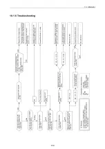
Page 157: ...9 Starting Motor 9 1 3 Troubleshooting 142 ...
Page 172: ...9 Starting Motor 9 2 3 Troubleshooting 157 ...
Page 175: ...9 Starting Motor 2 Removal of magnetic switch Remove the M6 bolts 10mm 2 160 ...
Page 185: ...9 Starting Motor 3 Brush 1 Check wear of the brush and the brush spring force 170 ...
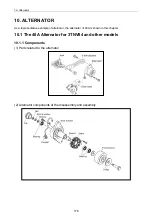
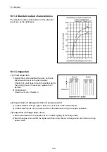
Page 194: ...10 Alternator 179 10 1 6 Troubleshooting ...
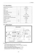
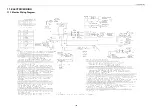
Page 195: ...11 Electric Wiring 180 11 ELECTRIC WIRING 11 1 Electric Wiring Diagram ...
Page 213: ......


