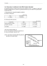
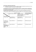
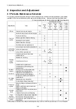
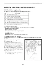
2. Inspection and Adjustment
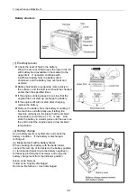
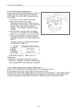
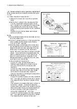
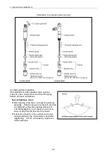
Battery structure
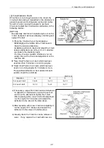
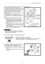
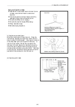
(1) Electrolyte level
Check the level of fluid in the battery.
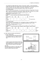
When the amount of fluid nears the lower limit, fill
with battery fluid (available in the market) to the
upper limit. If operation continues with
insufficient battery fluid, the battery life is
shortened, and the battery may overheat and
explode.
Battery fluid tends to evaporate more quickly in
the summer, and the fluid level should be checked
earlier than the specified times.
If the engine cranking speed is so slow that the
engine does not start up, recharge the battery.
If the engine still will not start after charging,
replace the battery.
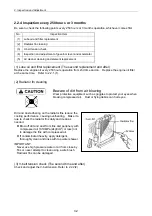
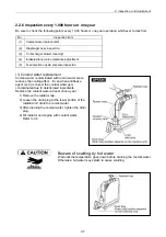
Remove the battery from the battery mounting of
the machine unit after daily use if letting the
machine unit leave in the place that the ambient
temperature could drop at -15 or less. And
store the battery in a warm place until the next use
the unit to start the engine easily at low ambient
temperature.
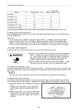
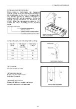
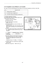
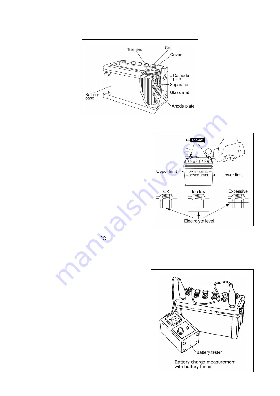
(2) Battery charge
Use a battery tester or hydrometer and check the
battery condition. If the battery is discharged,
recharge it.
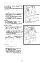
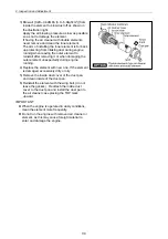
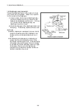
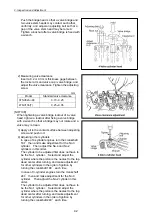
(a) Measurement with a battery tester
When checking the battery with the batter tester,
connect the red clip of the tester to the battery positive
(+) terminal and black clip to the battery negative (-)
terminal by pinching them securely, and judge the
battery charge level from the indicator position.
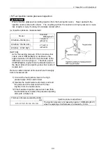
Green zone: Normal
Yellow zone: Slightly discharged
Red zone: Defective or much discharged
30
Summary of Contents for 3TNV Series
Page 1: ...4TNV106 4TNV106T 4TNV94L 4TNV98 4TNV98T 3TNV82A 3TNV84 T 4TNV84 T 3TNV88 4TNV88 ...
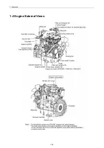
Page 31: ...1 General 1 4 Engine External Views 16 ...
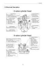
Page 32: ...1 General 1 5 Structural Description 17 ...
Page 156: ...9 Starting Motor 9 1 2 Components 141 ...
Page 157: ...9 Starting Motor 9 1 3 Troubleshooting 142 ...
Page 172: ...9 Starting Motor 9 2 3 Troubleshooting 157 ...
Page 175: ...9 Starting Motor 2 Removal of magnetic switch Remove the M6 bolts 10mm 2 160 ...
Page 185: ...9 Starting Motor 3 Brush 1 Check wear of the brush and the brush spring force 170 ...
Page 194: ...10 Alternator 179 10 1 6 Troubleshooting ...
Page 195: ...11 Electric Wiring 180 11 ELECTRIC WIRING 11 1 Electric Wiring Diagram ...
Page 213: ......


