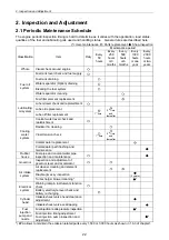
2. Inspection and Adjustment
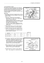
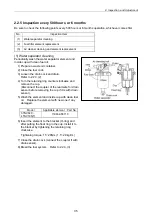
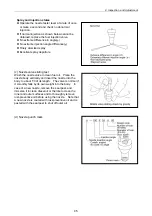
(4) Inspection and adjustment of governor lever and accelerator
The governor lever and accelerating devices
(accelerating lever, pedal, etc.) of the machine unit are
connected by an accelerating wire or rod. If the wire
becomes stretched or the connections loose, the
deviation in the position may result and make
operation unsafe. Check the wire periodically and
djust if necessary.
a
Do not strongly move the accelerating wire or
accelerating pedal. It may deform the governor lever
or stretch the wire to cause irregular engine speed
control.
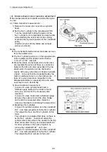
Checking and adjusting procedure are as follows.
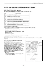
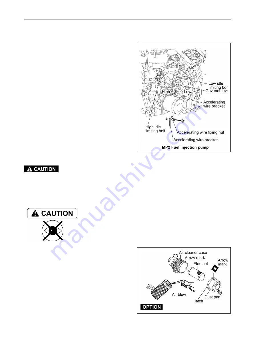
1) Check that the governor lever of the engine
makes uniform contact with the high idling and
low idling limiting bolt when the accelerating
devices is in the high idling speed or low idling
speed position.
2) If either the high or the low idling speed side does
not make contact with the limiting bolt, adjust the
accelerating wire.
Loosen the accelerating wire fixing nut and adjust
the wire to contact with the limitng bolt.
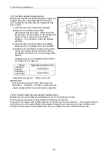
Never release the limiting bolts. It will impair the
safety and performance of the product and functions
and result in shorter engine life.
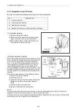
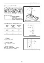
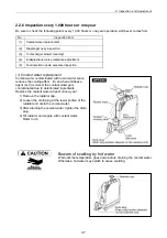
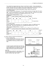
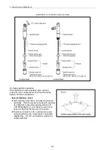
(5) Air cleaner cleaning and element replacement
B
eware of dirt from air blowing
Wear protective equipment such as goggles to protect your eyes when
blowing compressed air. Dust or flying debris can hurt eyes.
The engine performance is adversely affected when
the air cleaner element is clogged by dust. So
periodical cleaning after disassembly is needed.
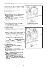
1) Undo the clamps on the dust pan and remove the
dust pan.
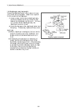
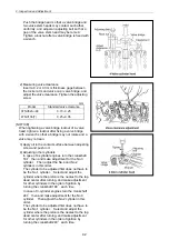
2) Loosen the wing bolt on the element and pull out
the element.
33
Summary of Contents for 3TNV Series
Page 1: ...4TNV106 4TNV106T 4TNV94L 4TNV98 4TNV98T 3TNV82A 3TNV84 T 4TNV84 T 3TNV88 4TNV88 ...
Page 31: ...1 General 1 4 Engine External Views 16 ...
Page 32: ...1 General 1 5 Structural Description 17 ...
Page 156: ...9 Starting Motor 9 1 2 Components 141 ...
Page 157: ...9 Starting Motor 9 1 3 Troubleshooting 142 ...
Page 172: ...9 Starting Motor 9 2 3 Troubleshooting 157 ...
Page 175: ...9 Starting Motor 2 Removal of magnetic switch Remove the M6 bolts 10mm 2 160 ...
Page 185: ...9 Starting Motor 3 Brush 1 Check wear of the brush and the brush spring force 170 ...
Page 194: ...10 Alternator 179 10 1 6 Troubleshooting ...
Page 195: ...11 Electric Wiring 180 11 ELECTRIC WIRING 11 1 Electric Wiring Diagram ...
Page 213: ......


