2. Inspection and Adjustment
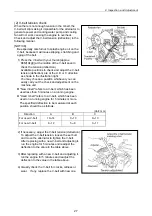
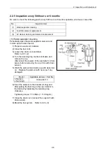
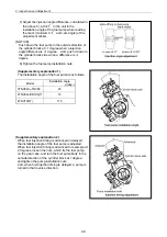
The cylinder to be adjusted first does not have to be the No.1 cylinder. Select and adjust the
cylinder where the piston is the nearest to the top dead center after turning, and make adjustment
for other cylinders in the order of ignition by turning the crankshaft 240 each time.
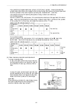
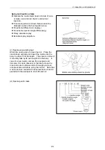
The adjustment method of reducing the flywheel turning numbers (for reference):
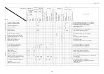
For 3 cylinder engines
Set No.1 cylinder to the compression T.D.C.and adjust the clearance of the mark of the below
table. Next, turn the flywheel once (the suction / exhaust valve of No.1 cylinder is in the position
of the overlap T.D.C. at this time), and adjust the clearance of the mark.
Ignition order of 3 cylinder engines: 1 3 2
Cylinder No.
1
2
3
Valve Suction
Exhaust
Suction Exhaust Suction Exhaust
No.1
compression
T.D.C
The first time
No.1
overlap
T.D.C
The second time
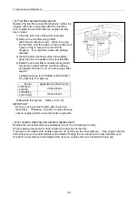
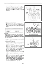
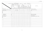
For 4 cylinder engines
Set No.1 cylinder to the compression T.D.C. and adjust the clearance of the mark of the
bottom table. Next, turn the flywheel once, and adjust the clearance of the mark.
Ignition order of 3 cylinder engines: 1 3 4 2
Cylinder No.
1
2
3
4
Valve
Suction Exhaust Suction Exhaust Suction Exhaust Suction Exhaust
No.1
compression
T.D.C
The first
time
No.4
compression
T.D.C
The
second
time
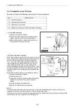
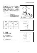
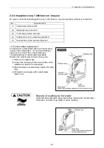
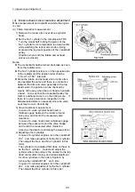
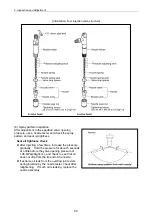
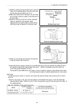
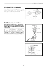
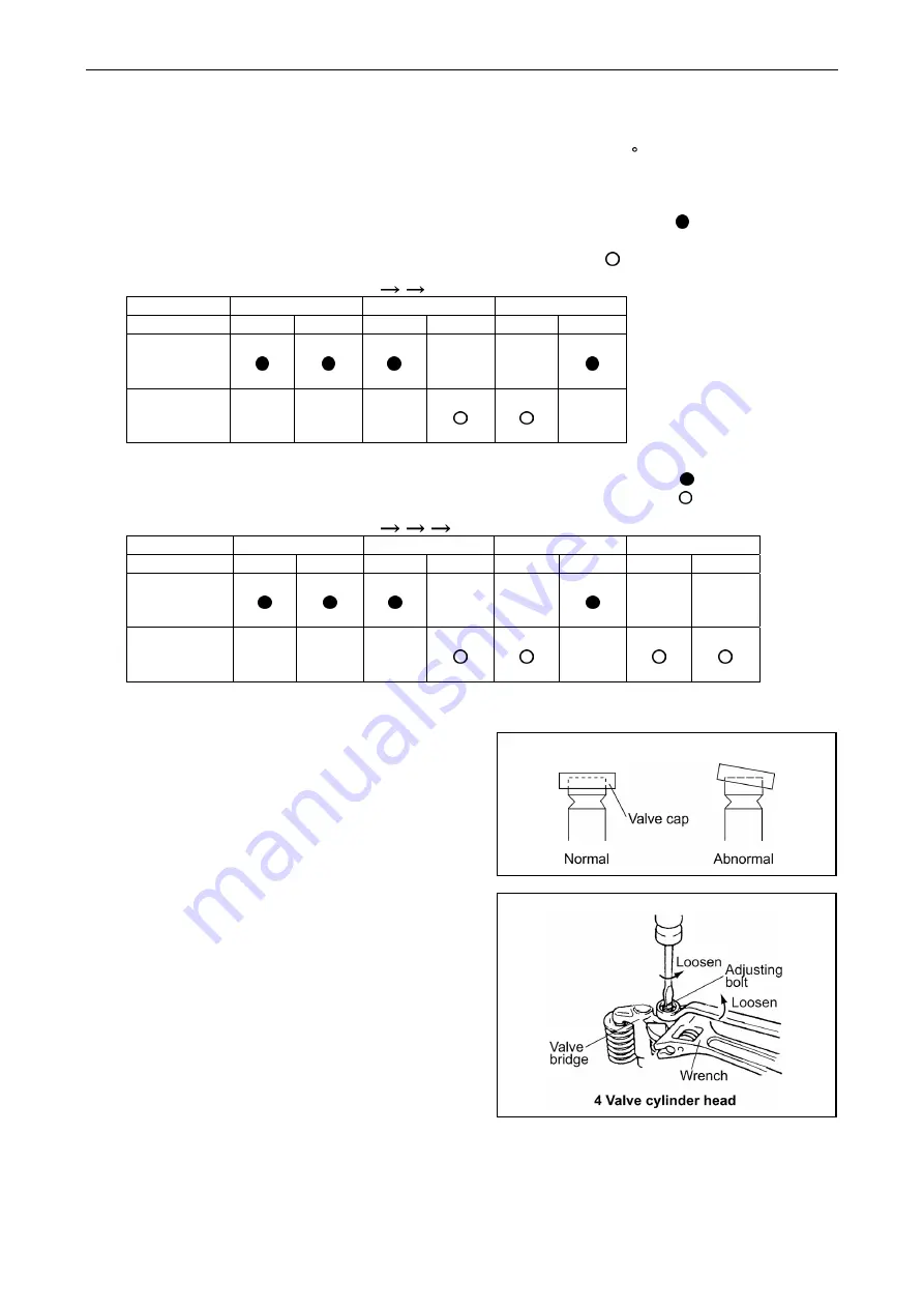
(b) Valve clearance inspection and adjustment
1) Loosen adjusting bolts
In case of 2-valve cylinder head loosen the lock
nut and adjusting screw, and check the valve for
any inclination of valve cap, entrance of dirt or
wear.
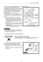
In case of 4-valve cylinder head loosen the lock
nut and adjusting screw of rocker arm. Be careful
that excessive tension isn't applied to the valve
bridge, and loosen a locknut of valve bridge.
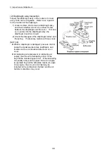
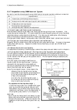
[NOTICE]
When loosening a locknut of a valve bridge, loosen
the locknut while fixing the valve bridge with a
wrench so that the valve may not lean.
41
Summary of Contents for 3TNV Series
Page 1: ...4TNV106 4TNV106T 4TNV94L 4TNV98 4TNV98T 3TNV82A 3TNV84 T 4TNV84 T 3TNV88 4TNV88 ...
Page 31: ...1 General 1 4 Engine External Views 16 ...
Page 32: ...1 General 1 5 Structural Description 17 ...
Page 156: ...9 Starting Motor 9 1 2 Components 141 ...
Page 157: ...9 Starting Motor 9 1 3 Troubleshooting 142 ...
Page 172: ...9 Starting Motor 9 2 3 Troubleshooting 157 ...
Page 175: ...9 Starting Motor 2 Removal of magnetic switch Remove the M6 bolts 10mm 2 160 ...
Page 185: ...9 Starting Motor 3 Brush 1 Check wear of the brush and the brush spring force 170 ...
Page 194: ...10 Alternator 179 10 1 6 Troubleshooting ...
Page 195: ...11 Electric Wiring 180 11 ELECTRIC WIRING 11 1 Electric Wiring Diagram ...
Page 213: ......


