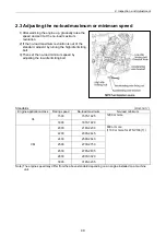
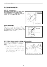
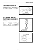
2. Inspection and Adjustment
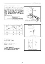
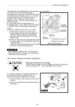
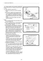
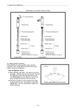
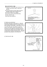
(5) Fuel injection nozzle pressure inspection
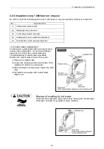
Wear protective glasses when testing injection from the fuel injection valve. Never approach the
injection nozzle portion with a hand. The oil jetting out from the nozzle is at a high pressure to cause
loss of sight or injury if coming into careless contact with it.
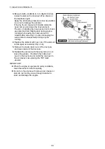
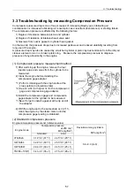
(a) Injection pressure measurement
Model
Standard
MPa(kgf/cm
2
)
3TNV82A TNV88 (CL )
19.6-20.6
(200-210)
3TNV82A TNV88 (VM )
4TNV94L 4TNV106(T)
21.6-22.6
(220-230)
[NOTICE]
As for the opening pressure of the brand-new fuel
nozzle, about 0.5Mpa(5kgf/cm) declines by the
engine operation for about 5 hours because of the
initial wear-out of a spring etc. Therefore, adjust
0.5MPa(5kgf/cm) higher than the standard value of
the above table when adjusting a new fuel nozzle of
a spare part.
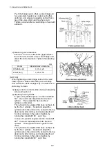
Remove carbon deposit at the nozzle hole thoroughly
before measurement.
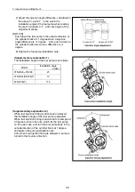
1) Connect the fuel injection valve to the high
pressure pipe of the nozzle tester.
2) Operate the nozzle tester lever slowly and read
the pressure at the moment when the fuel
injection from the nozzle starts.
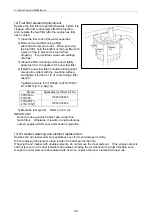
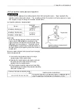
3) If the measured injection pressure is lower than
the standard level, replace the pressure adjusting
shim with a thicker one.
Thickness of pressure adjusting shims
mm
Injection pressure adjustment
0.13, 0.15, 0.18, 0.4, 0.5, 0.8
The injection pressure is increased by approx. l.9 MPa(l9 kgf/cm
2
),
when the adjusting shim thickness is increased by 0.l mm.
43
Summary of Contents for 3TNV Series
Page 1: ...4TNV106 4TNV106T 4TNV94L 4TNV98 4TNV98T 3TNV82A 3TNV84 T 4TNV84 T 3TNV88 4TNV88 ...
Page 31: ...1 General 1 4 Engine External Views 16 ...
Page 32: ...1 General 1 5 Structural Description 17 ...
Page 156: ...9 Starting Motor 9 1 2 Components 141 ...
Page 157: ...9 Starting Motor 9 1 3 Troubleshooting 142 ...
Page 172: ...9 Starting Motor 9 2 3 Troubleshooting 157 ...
Page 175: ...9 Starting Motor 2 Removal of magnetic switch Remove the M6 bolts 10mm 2 160 ...
Page 185: ...9 Starting Motor 3 Brush 1 Check wear of the brush and the brush spring force 170 ...
Page 194: ...10 Alternator 179 10 1 6 Troubleshooting ...
Page 195: ...11 Electric Wiring 180 11 ELECTRIC WIRING 11 1 Electric Wiring Diagram ...
Page 213: ......


