2. Inspection and Adjustment
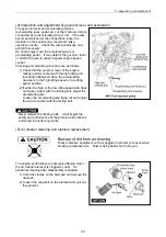
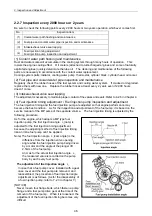
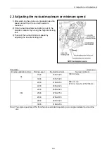
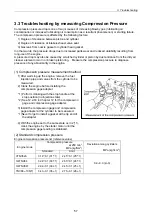
1) Before removing a fuel pump drive gear, make ID
marks on the gearing part of the pump drive gear
and the idle gear with paint and so on.
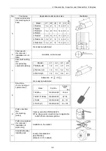
2) Make the mark-off line to the gear case precisely
in accordance with the position of mark-off line of
the fuel pump.
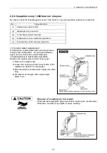
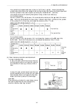
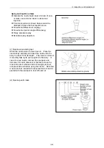
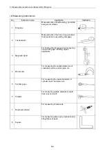
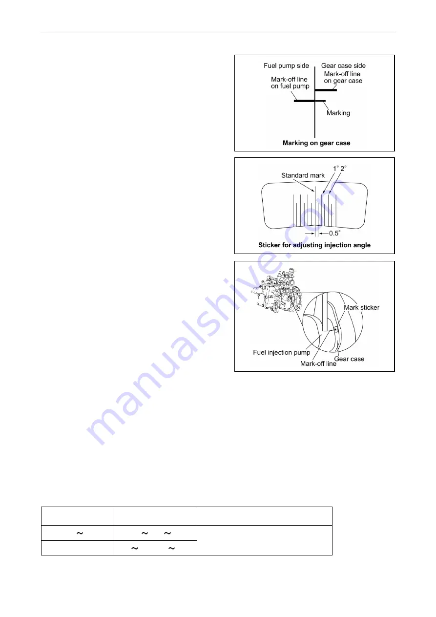
3) Before removing a fuel pump, put the standard
mark of a sticker for fuel injection angle
adjustment in accordance with the mark-off line
of the fuel pump and paste it on the gear case.
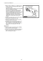
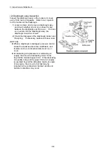
4) Remove a fuel pump, and read the fuel injection
angle recorded in that fuel pump.
5) Read the injection angle recorded on a reassembled fuel pump and calculate the difference from
the injection angle of the disassembled fuel pump. (When re-installation does the same fuel
pump, the angular difference is zero.)
Fuel injection angle difference (cam angle) = (the fuel injection angle of a reassembled fuel pump)
- (the fuel injection angle of a disassembled previous fuel pump)
[NOTICE]
Tell the fuel pump number to Yanmar, and inquire the injection angle of the pump when it is hard to
find out.
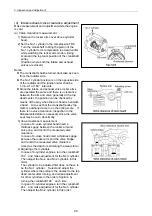
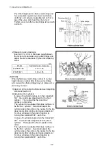
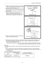
6) Put the fuel pump on the gear case temporarily and install the drive gear on the cam shaft with
checking the ID marks, which were put on the fuel pump drive gear and the idle gear at the time of
the disassembling.
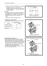
Tighten the installation nut of a pump drive gear.
Model
Tightening torque
Nm(kgf
・
m)
Lubricating oil application
(thread portion, and seat surface)
3TNV82A TNV88 78 88 (8 9)
4TNV94L/98/106(T) 113 123 (11.5 12.5)
Not applied
47
Summary of Contents for 3TNV Series
Page 1: ...4TNV106 4TNV106T 4TNV94L 4TNV98 4TNV98T 3TNV82A 3TNV84 T 4TNV84 T 3TNV88 4TNV88 ...
Page 31: ...1 General 1 4 Engine External Views 16 ...
Page 32: ...1 General 1 5 Structural Description 17 ...
Page 156: ...9 Starting Motor 9 1 2 Components 141 ...
Page 157: ...9 Starting Motor 9 1 3 Troubleshooting 142 ...
Page 172: ...9 Starting Motor 9 2 3 Troubleshooting 157 ...
Page 175: ...9 Starting Motor 2 Removal of magnetic switch Remove the M6 bolts 10mm 2 160 ...
Page 185: ...9 Starting Motor 3 Brush 1 Check wear of the brush and the brush spring force 170 ...
Page 194: ...10 Alternator 179 10 1 6 Troubleshooting ...
Page 195: ...11 Electric Wiring 180 11 ELECTRIC WIRING 11 1 Electric Wiring Diagram ...
Page 213: ......


