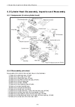
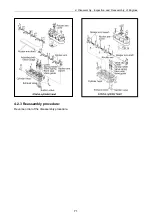
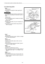
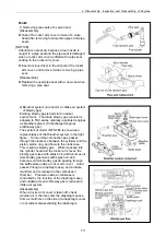
4. Disassembly, Inspection and Reassembly of Engines
60
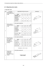
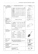
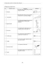
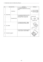
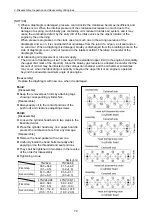
4.1.2 Special service tools
(1) Special Tools
No.
Tool name
Applicable model and tool size
Illustration
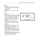
1
Valve guide tool
(for extracting valve
guide)
㎜
Model
L1 L2 d1 d2
3TNV82A
4TNV94L 98(T)
4TNV106(T)
20 75 6.5
10
4TNV84
3TNV84(T)
3/4TNV88
20 75 7.5
11
4TNV84T 20
75
5.5
9
※
Locally manufactured
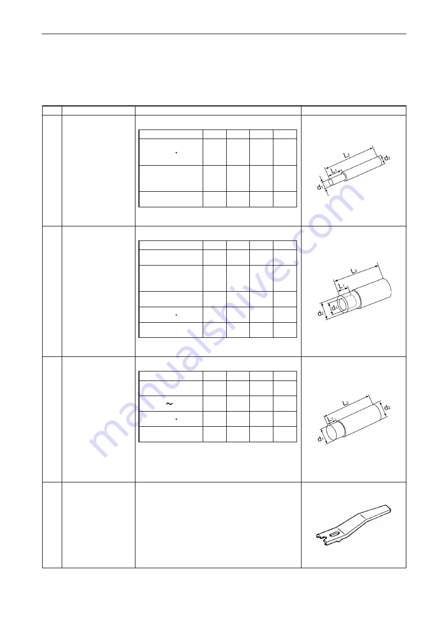
2
Valve guide tool
(for inserting valve
guide)
㎜
Model
L1 L2 d1 d2
3TNV82A
12 60 13 19
4TNV84
3TNV84(T)
3/4TNV88
15 65 14 20
4TNV84T
8.5
60 11 17
4TNV94L 98(T)
7 60 13 16
4TNV106(T) 13.6
65 13 16
※
Locally manufactured
3
Connecting rod
bushing replacer
(for removal /
installation of
connecting rod
bushing)
㎜
Model
L1 L2 d1 d2
3TNV82A
25 85 23 26
TNV84 88 20
100
26
29
4TNV94L 98 20
100
30
33
4TNV106(T) 20
100
37
40
Allowance:
3
.
0
6
.
0
1
d
−
−
3
.
0
6
.
0
2
d
−
−
※
Locally manufactured
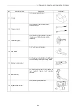
4
Valve spring
compressor
(for removal /
installation of valve
spring)
yanmar code No.
129100-92630
Summary of Contents for 3TNV Series
Page 1: ...4TNV106 4TNV106T 4TNV94L 4TNV98 4TNV98T 3TNV82A 3TNV84 T 4TNV84 T 3TNV88 4TNV88 ...
Page 31: ...1 General 1 4 Engine External Views 16 ...
Page 32: ...1 General 1 5 Structural Description 17 ...
Page 156: ...9 Starting Motor 9 1 2 Components 141 ...
Page 157: ...9 Starting Motor 9 1 3 Troubleshooting 142 ...
Page 172: ...9 Starting Motor 9 2 3 Troubleshooting 157 ...
Page 175: ...9 Starting Motor 2 Removal of magnetic switch Remove the M6 bolts 10mm 2 160 ...
Page 185: ...9 Starting Motor 3 Brush 1 Check wear of the brush and the brush spring force 170 ...
Page 194: ...10 Alternator 179 10 1 6 Troubleshooting ...
Page 195: ...11 Electric Wiring 180 11 ELECTRIC WIRING 11 1 Electric Wiring Diagram ...
Page 213: ......


