4. Disassembly, Inspection and Reassembly of Engines
67
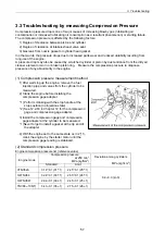
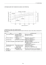
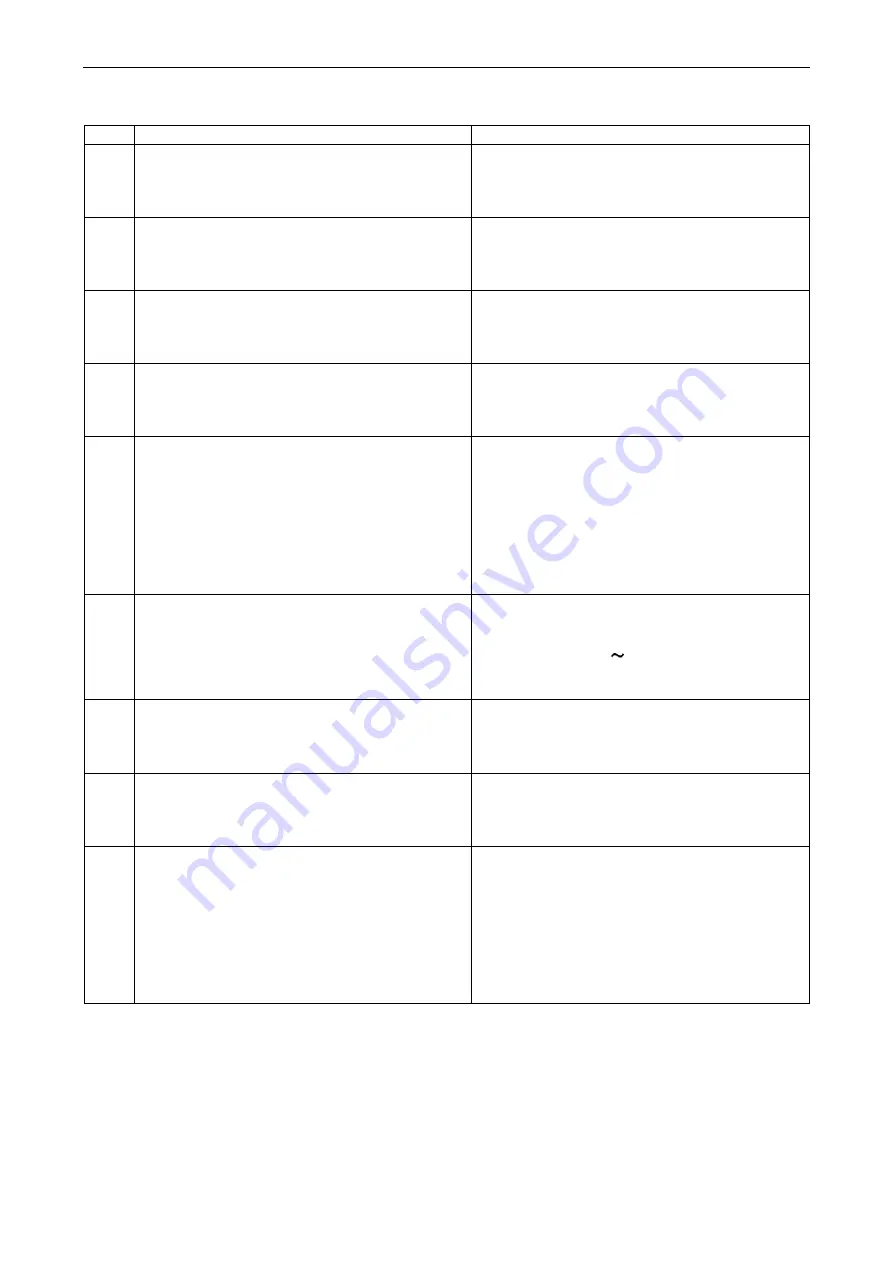
Step Removal
Parts
Remarks
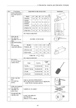
14
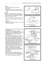
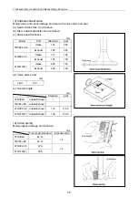
1) Remove lubricating oil pump.
15
1) Remove starting motor from flywheel housing
sing.
16
1) Remove flywheel mounting bolt.
2) Remove flywheel.
1) Carefully protect the ring gear from damage
mage.
17
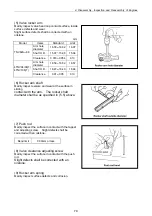
1) Remove flywheel housing.
2) Remove oil seal case with a screwdriver or
the like by utilizing grooves on both sides of
oil seal case.
1) Carefully protect the oil seal from damage.
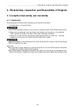
18
1) Remove oil pan and spacer.
1) Put the cylinder block with the attaching
surface of the cylinder head facing down.
2) Carefully protect the combustion surface of
the cylinder block from damage.
3) For indirect injection system, be careful to the
possibility of the tapped to drop off when the
cylinder block is turned upside down,
because the tappet is cylindrical in shape.
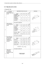
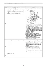
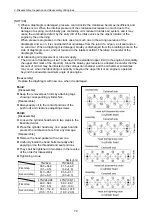
19
1) Remove idle gear shaft, and then remove idle
gear.
2) Remove mounting bolt of thrust bearing
through the hole of the camshaft gear.
Remove camshaft assembly.
1) Turn the cylinder block aside and carefully
prevent tappet from jamming on the cam.
2) Preheat camshaft gear and camshaft
assembly to 180° 200° which are shrink
fitted, before removing them.
20
1) Remove gear case flange.
21
1) Remove lubricating oil strainer.
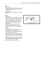
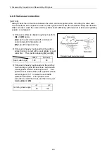
22
1) Remove crankpin side cap of the connecting
rod.
While turning crankshaft, place piston in the
bottom dead center (BDC).
1) Before extracting piston, remove carbon
deposits from the upper wall of the cylinder
using fine sandpaper, while taking care not to
damage the inner surface of the cylinder.
2) Make sure than cap No. of connecting rod
agrees with cylinder No.
3) Take care not to let crankpin metal fall when
removing connecting rod crankpin side cap.
Summary of Contents for 3TNV Series
Page 1: ...4TNV106 4TNV106T 4TNV94L 4TNV98 4TNV98T 3TNV82A 3TNV84 T 4TNV84 T 3TNV88 4TNV88 ...
Page 31: ...1 General 1 4 Engine External Views 16 ...
Page 32: ...1 General 1 5 Structural Description 17 ...
Page 156: ...9 Starting Motor 9 1 2 Components 141 ...
Page 157: ...9 Starting Motor 9 1 3 Troubleshooting 142 ...
Page 172: ...9 Starting Motor 9 2 3 Troubleshooting 157 ...
Page 175: ...9 Starting Motor 2 Removal of magnetic switch Remove the M6 bolts 10mm 2 160 ...
Page 185: ...9 Starting Motor 3 Brush 1 Check wear of the brush and the brush spring force 170 ...
Page 194: ...10 Alternator 179 10 1 6 Troubleshooting ...
Page 195: ...11 Electric Wiring 180 11 ELECTRIC WIRING 11 1 Electric Wiring Diagram ...
Page 213: ......


