4. Disassembly, Inspection and Reassembly of Engines
68
Step Removal
Parts
Remarks
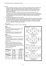
23
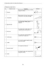
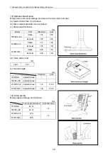
1) Remove main bearing cap bolt. While
shaking main bearing cap, remove main
bearing cap together with lower main bearing
metal.
2) Extract crankshaft, taking care not to damage
it.
3) Remove upper main bearing metal.
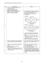
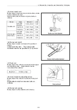
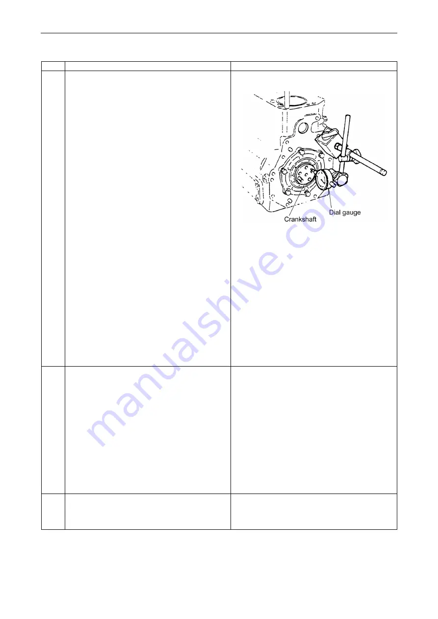
1) Before extracting crankshaft, measure the
side gap around it.
Apply a dial gauge to the end of crankshaft.
Force the crankshaft on both sides in the axial
direction to measure the thrust gap.
Alternatively, insert a thickness gauge directly
between the base thrust metal and the thrust
surface of the crankshaft to measure the gap.
If the limit size is exceeded, replace the thrust
metal with a new one.
Thrust gap (All models)
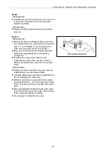
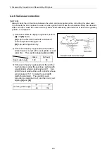
2) Notice on the removal of thrust metal.
a) When removing thrust metal, ascertain the
position and direction where thrust metal is
installed in relation to the cap.
b) Make sure that the thrust metal groove is
outward in relation to the cap.
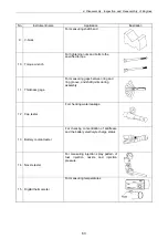
24
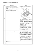
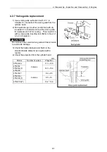
1) Remove piston and connecting rod assembly.
1) To selectively remove a desired piston and
connecting rod assembly without extracting
crankshaft, take the steps itemized below:
a) Remove carbon deposits from the upper wall
of the cylinder using fine sandpaper, taking
care not to damage the inner surface of the
cylinder.
b) While turning the crankshaft, with the
connecting rod cap removed, raise the
piston up to the top dead center (TDC).
c) Extract the piston/connecting rod assembly
while tapping the connecting rod at the large
end with the handle of a plastic hammer or the
like.
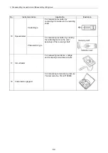
25
2) Remove tappet.
Summary of Contents for 3TNV Series
Page 1: ...4TNV106 4TNV106T 4TNV94L 4TNV98 4TNV98T 3TNV82A 3TNV84 T 4TNV84 T 3TNV88 4TNV88 ...
Page 31: ...1 General 1 4 Engine External Views 16 ...
Page 32: ...1 General 1 5 Structural Description 17 ...
Page 156: ...9 Starting Motor 9 1 2 Components 141 ...
Page 157: ...9 Starting Motor 9 1 3 Troubleshooting 142 ...
Page 172: ...9 Starting Motor 9 2 3 Troubleshooting 157 ...
Page 175: ...9 Starting Motor 2 Removal of magnetic switch Remove the M6 bolts 10mm 2 160 ...
Page 185: ...9 Starting Motor 3 Brush 1 Check wear of the brush and the brush spring force 170 ...
Page 194: ...10 Alternator 179 10 1 6 Troubleshooting ...
Page 195: ...11 Electric Wiring 180 11 ELECTRIC WIRING 11 1 Electric Wiring Diagram ...
Page 213: ......


