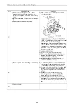
4. Disassembly, Inspection and Reassembly of Engines
70
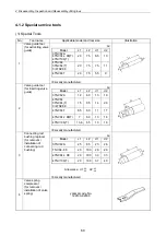
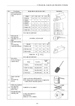
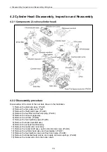
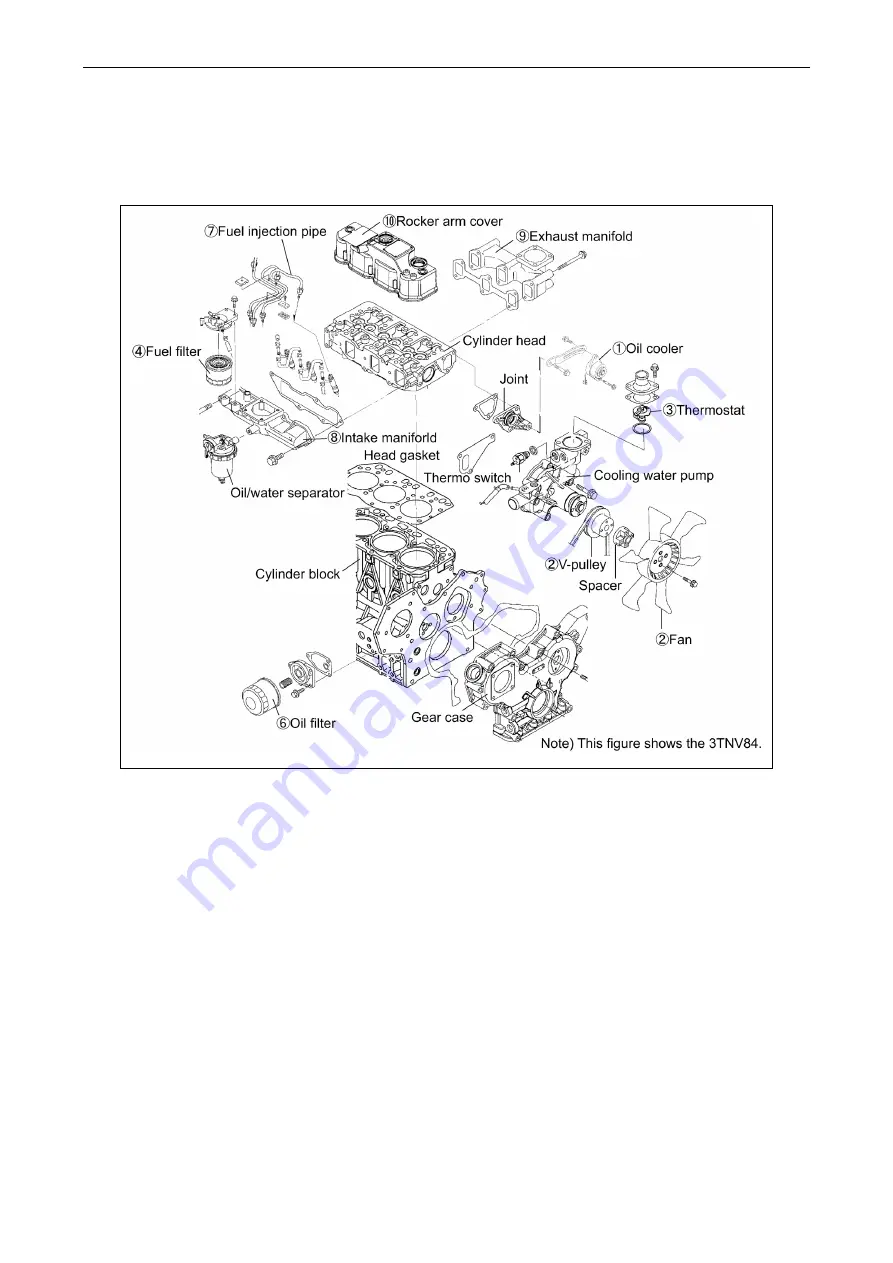
4.2 Cylinder Head: Disassembly, Inspection and Reassembly
4.2.1 Components (2-valve cylinder head)
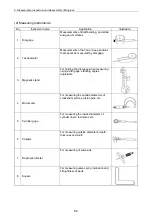
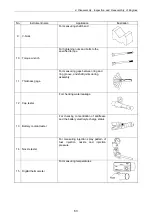
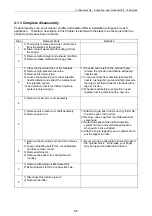
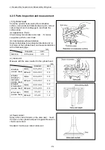
4.2.2 Disassembly procedure:
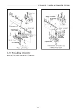
Disassemble in the order of the numbers shown in the illustration.
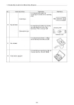
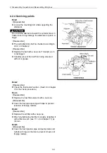
1) Remove the alternator assy. (Point1)
2) Remove the fan, pulley and V belt.
3) Remove the thermostat case. (Point2)
4) Remove the fuel filter and fuel oil piping. (Point3)
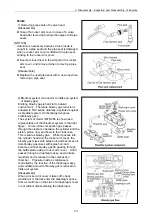
5) Remove the oil level gage assy.
6) Remove the oil filter. (Point4)
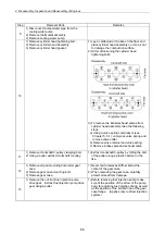
7) Remove the fuel injection pipes. (Point5)
8) Remove the intake manifold assy.
9) Remove the exhaust manifold assy.
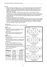
10) Remove the rocker arm cover Assy.
11) Remove the rocker shaft assy, push rods and valve caps. (Point6)
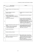
12) Remove the cylinder head assy and head gasket. (Point7)
13) Remove the fuel injection valves and fuel return pipe. (Point8)
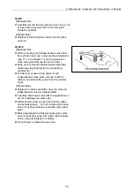
14) Remove the intake/exhaust valves, stem seals and valve springs. (Point9)
15) Remove the rocker arms from the rocker shaft.
Summary of Contents for 3TNV Series
Page 1: ...4TNV106 4TNV106T 4TNV94L 4TNV98 4TNV98T 3TNV82A 3TNV84 T 4TNV84 T 3TNV88 4TNV88 ...
Page 31: ...1 General 1 4 Engine External Views 16 ...
Page 32: ...1 General 1 5 Structural Description 17 ...
Page 156: ...9 Starting Motor 9 1 2 Components 141 ...
Page 157: ...9 Starting Motor 9 1 3 Troubleshooting 142 ...
Page 172: ...9 Starting Motor 9 2 3 Troubleshooting 157 ...
Page 175: ...9 Starting Motor 2 Removal of magnetic switch Remove the M6 bolts 10mm 2 160 ...
Page 185: ...9 Starting Motor 3 Brush 1 Check wear of the brush and the brush spring force 170 ...
Page 194: ...10 Alternator 179 10 1 6 Troubleshooting ...
Page 195: ...11 Electric Wiring 180 11 ELECTRIC WIRING 11 1 Electric Wiring Diagram ...
Page 213: ......


