4. Disassembly, Inspection and Reassembly of Engines
74
[NOTICE]
1) When a diaphragm is damaged, pressure control inside the crankcase becomes insufficient, and
troubles occur. When the internal pressure of the crankcase decreases too much due to the
damage of a spring, much blowby gas containing oil is reduced in intake air system, and it may
cause the combustion defect by the early dirt of the intake valve or the urgent rotation of the
engine by the oil burning.
When pressure progresses in the crank case too much due to the wrong operation of the
diaphragm and so on, it is considered that oil leakage from the joint of a oil pan, a oil seal and so
on will occur. When a diaphragm is damaged, blowby is discharged from the breathing hole on the
side of diaphragm cover, and not reduced in the intake manifold. Therefore, be careful of the
diaphragm trouble.
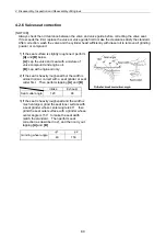
2) At lubricating oil replacement or lube oil supply
The amount of lubricating oil isn't to be beyond the standard upper limit (in the engine horizontality,
the upper limit mark of the dip stick). Since the blowby gas reductor is adopted, be careful that the
amount of oil mist may be inducted in the combustion chamber and the oil hammer sometimes
may occur, when the lubricating oil quantity is beyond the upper limit or an engine is operated
beyond the allowable maximum angle of an engine.
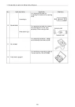
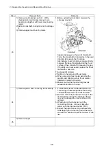
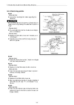
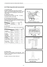
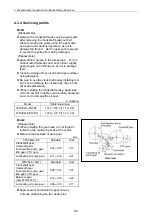
[Reassembly]
Replace the diaphragm with new one, when it is damaged.
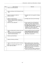
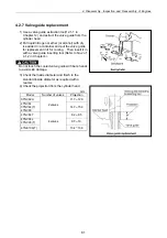
Point7
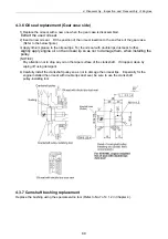
[Disassemble]
Keep the removed push rods by attaching tags
showing corresponding cylinder Nos.
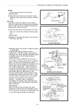
[Reassemble]
Always apply oil to the contact portions of the
push rods and clearance adjusting screws.
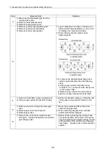
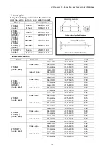
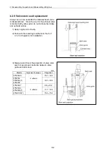
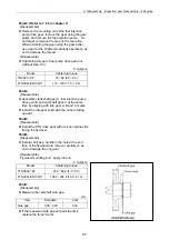
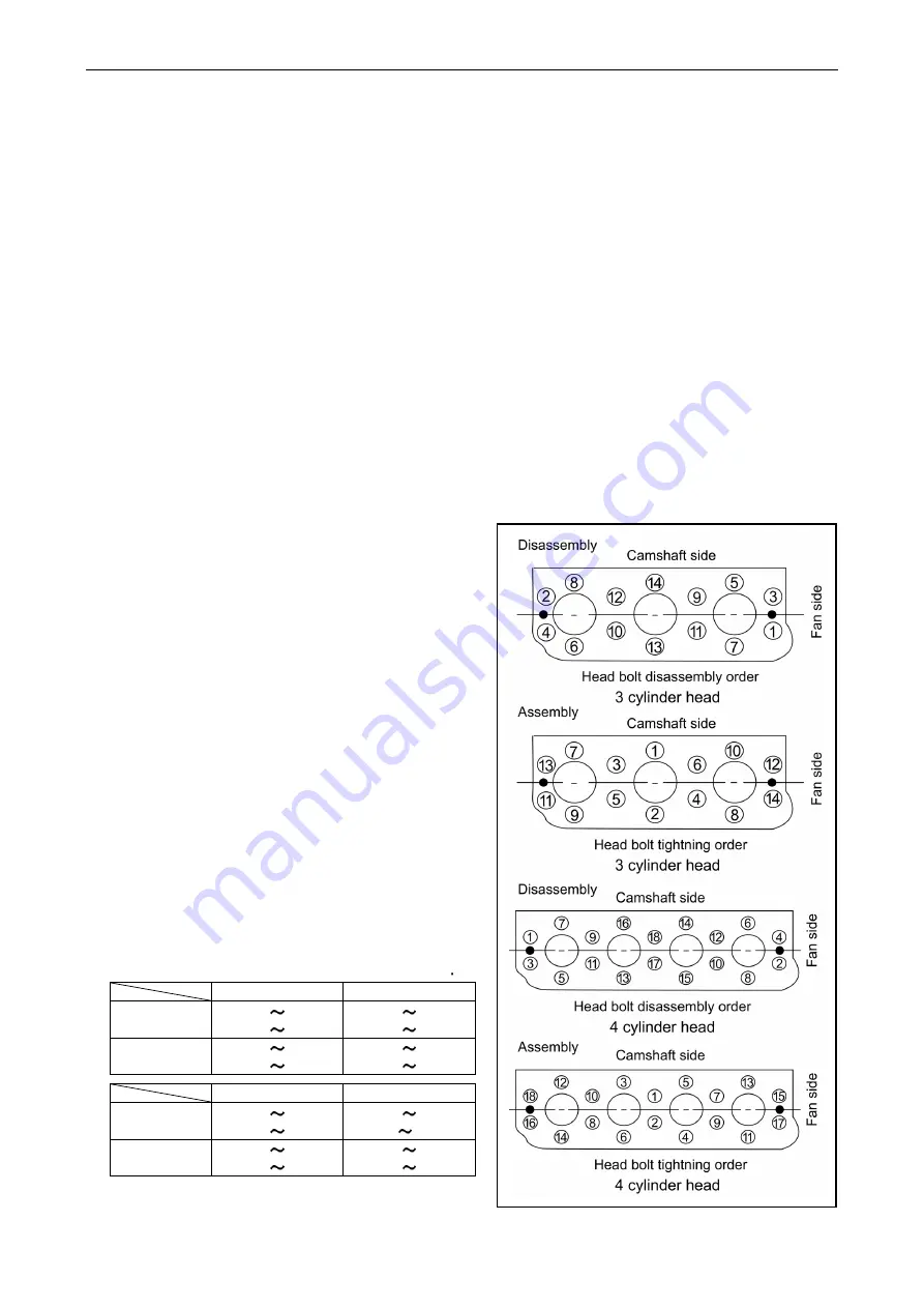
Point8
[Disassemble]
Loosen the cylinder head bolts in two steps in the
illustrated order.
Place the cylinder head assy on a paper board to
prevent the combustion face from any damage.
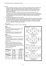
[Reassemble]
Remove the head gasket with a new one.
Uniformly install the head bolts manually after
applying oil on the threaded and seat portions
They shall be tightened in two steps in the reverse
of the order for disassembly.
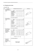
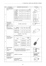
Tightening torque
Nm(kgf m)
TNV82A
TNV84-88
First step
30.0 34.0
(3.1 3.5)
41.1 46.9
(4.2 4.8)
Second step
61.7 65.7
(6.3 6.7)
85.3 91.1
(8.7 9.3)
4TNV94L/98
4TNV106(T)
First step
49.0 58.8
(5.0 6.0)
88.3 98.1
(9.0 10.0)
Second step
103.1 112.9
(10.5 11.5)
188.0 197.8
(19.0 20.0)
Summary of Contents for 3TNV Series
Page 1: ...4TNV106 4TNV106T 4TNV94L 4TNV98 4TNV98T 3TNV82A 3TNV84 T 4TNV84 T 3TNV88 4TNV88 ...
Page 31: ...1 General 1 4 Engine External Views 16 ...
Page 32: ...1 General 1 5 Structural Description 17 ...
Page 156: ...9 Starting Motor 9 1 2 Components 141 ...
Page 157: ...9 Starting Motor 9 1 3 Troubleshooting 142 ...
Page 172: ...9 Starting Motor 9 2 3 Troubleshooting 157 ...
Page 175: ...9 Starting Motor 2 Removal of magnetic switch Remove the M6 bolts 10mm 2 160 ...
Page 185: ...9 Starting Motor 3 Brush 1 Check wear of the brush and the brush spring force 170 ...
Page 194: ...10 Alternator 179 10 1 6 Troubleshooting ...
Page 195: ...11 Electric Wiring 180 11 ELECTRIC WIRING 11 1 Electric Wiring Diagram ...
Page 213: ......


