ENGINE
6-48
TNV DI Service Manual
2-Valve Cylinder Head
6. Tighten the rocker arm shaft alignment studs.
7. Adjust the valve clearance. See Measuring and
Adjusting Valve Clearance on page 6-66.
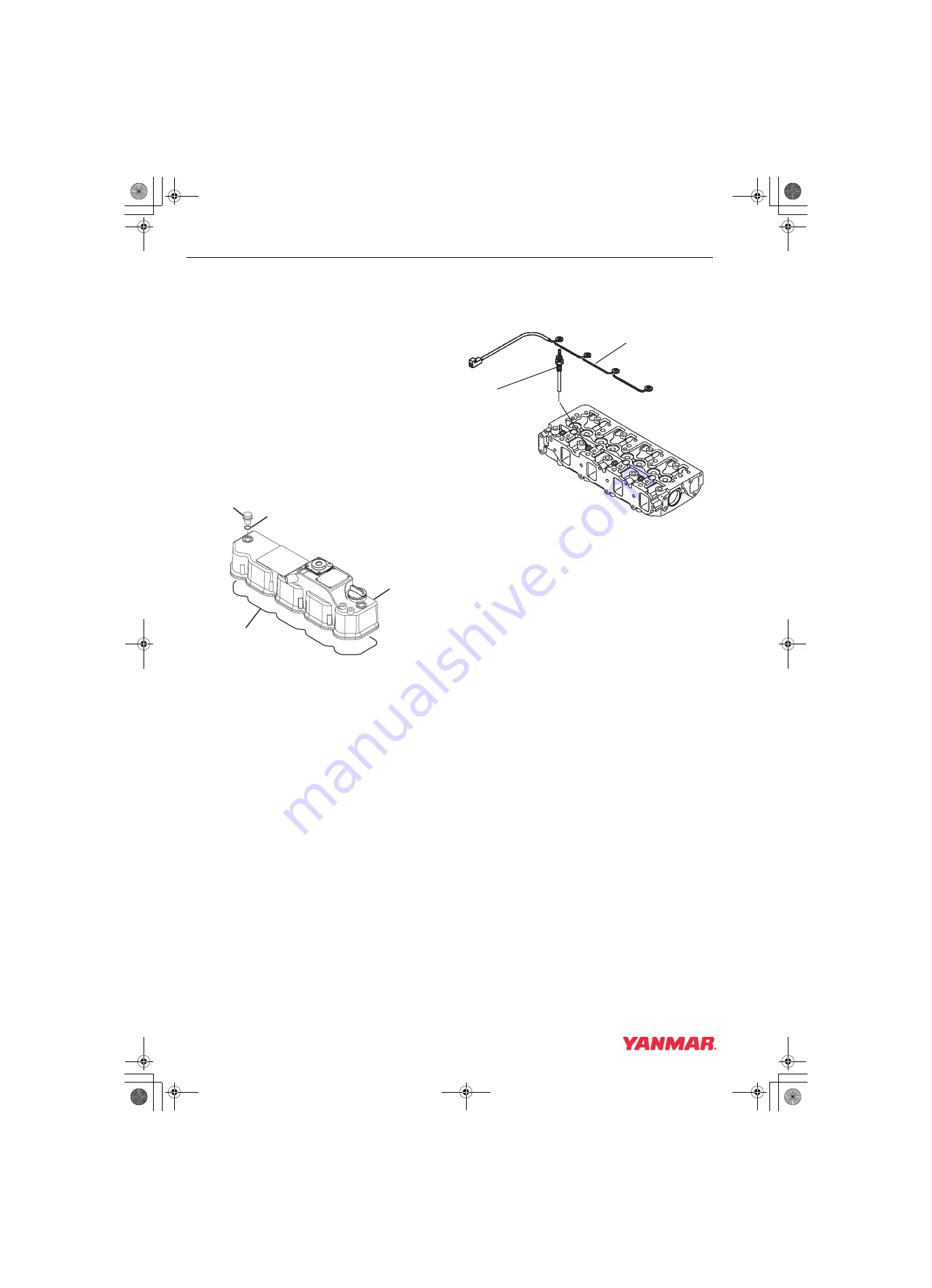
Reassembly of the Valve Cover
1. Lightly grease a new valve cover gasket
(Figure 6-37, (4)). Place the gasket in the
groove of the valve cover (Figure 6-37, (3)).
2. Place the valve cover on the cylinder head.
3. Be sure new O-rings (Figure 6-37, (2)) are
installed on the valve cover nuts. Reinstall and
tighten the valve cover nuts (Figure 6-37, (1)).
4. Reinstall the exhaust manifold using a new
gasket. Tighten the bolts to the specified
torque.
Figure 6-37
5. Reinstall the intake manifold using a new
gasket. Tighten the bolts to the specified
torque.
6. Install each glow plug (Figure 6-38, (1)), and
tighten it with the specified torque. Install each
electrical harness (Figure 6-38, (1)), and
tighten it with the specified torque.
Figure 6-38
7. Reinstall the fuel injectors. See Installation of
the Fuel Injectors on page 7-42.
8. Reinstall the high pressure and the return fuel
injection lines. See Installation of the Fuel
Injectors on page 7-42
9. Reinstall the engine coolant pump. See
Reassembly of Engine Coolant Pump on
page 8-11.
10. Reinstall the coolant hoses on the cold start
device on the fuel injection pump.
11. Reinstall the alternator. See Installation of
0001920
(4)
(3)
(1)
(2)
(2)
(1)
TNV_DI_SM_A4.book 48 ページ 2007年12月6日 木曜日 午前9時23分
Summary of Contents for 3TNV82A-B
Page 8: ...INTRODUCTION 1 2 TNV DI Service Manual This Page Intentionally Left Blank TNV_DI_SM_A4 book 2...
Page 18: ...SAFETY 3 2 TNV DI Service Manual This Page Intentionally Left Blank TNV_DI_SM_A4 book 2...
Page 320: ...TURBOCHARGER 10 2 TNV DI Service Manual This Page Intentionally Left Blank TNV_DI_SM_A4 book 2...


