ENGINE
TNV DI Service Manual
6-81
Crankshaft and Camshaft Components
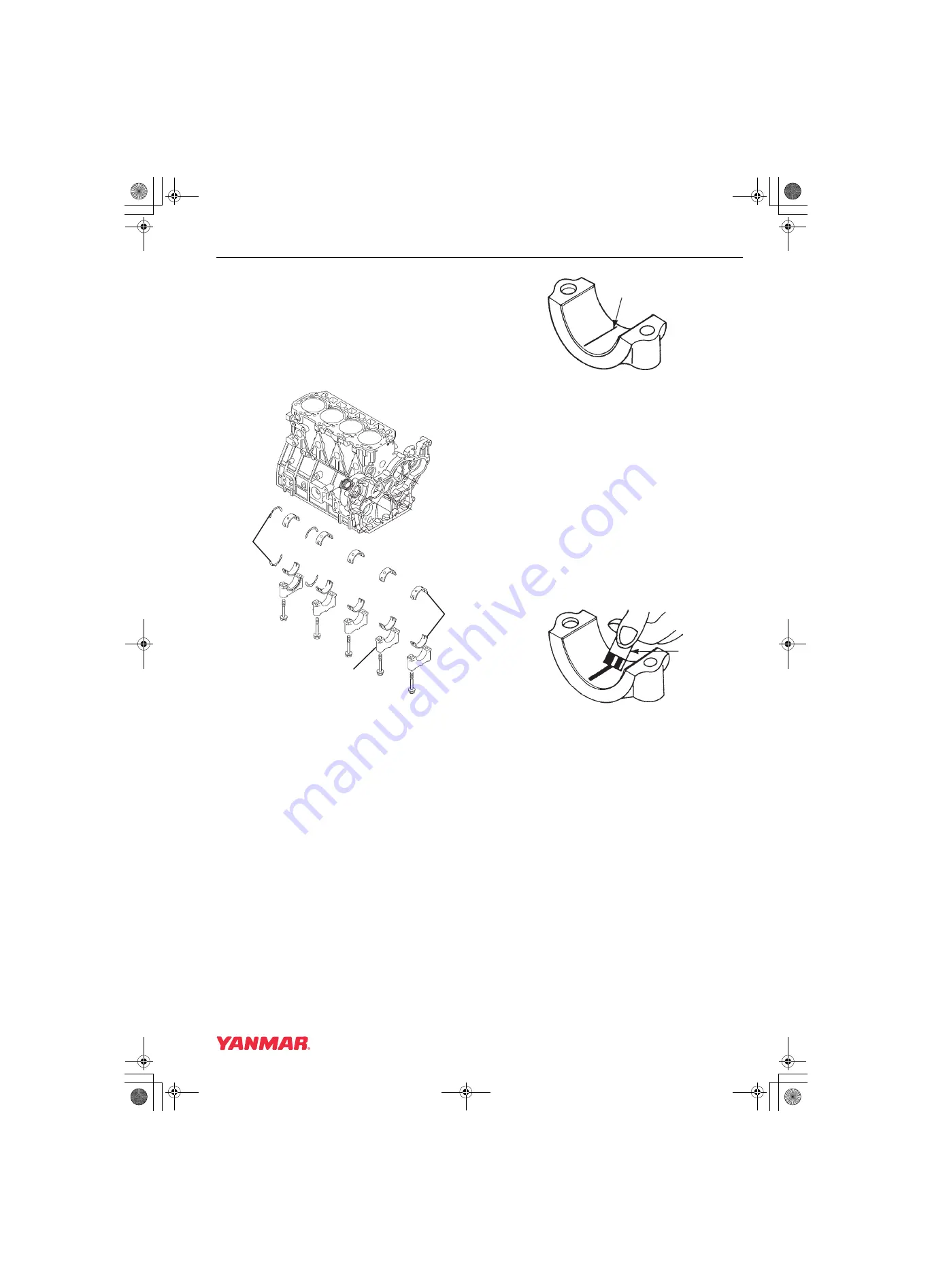
4. Remove the main bearing caps
(Figure 6-107, (3)). Be sure to note the
markings on the main bearing caps, or mark
them yourself, so they can be reinstalled in the
same order as they were removed. Do not
remove the bearing inserts at this time.
Note: The “arrows” on the main bearing caps
point to the flywheel end of the engine.
Figure 6-107
5. Measure bearing oil clearance prior to removing
the crankshaft to determine extent of wear.
Record the measurements.
(a) Wipe oil from the bearing insert and
crankshaft journal surfaces.
(b) Place a piece of PLASTIGAGE
(Figure 6-108, (1)) along the full width of
each bearing insert.
Figure 6-108
IMPORTANT
Do not rotate the crankshaft when using
PLASTIGAGE. A false reading may result.
(c) Reinstall bearing caps and tighten to
specification. See Special Torque Chart on
page 6-25.
(d) Remove bearing caps.
(e) Compare the width of the flattened
PLASTIGAGE to the graduation marks on
the package (Figure 6-109, (1)). The mark
that most closely matches the width of the
flattened PLASTIGAGE will indicate the
bearing oil clearance.
Figure 6-109
6. Remove the crankshaft from the engine.
7. Remove the bearing inserts (Figure 6-107, (1))
and thrust bearings (Figure 6-107, (2)).
Note: Do not remove the crankshaft gear
unless the gear or crankshaft are
damaged and require replacement.
(2)
0001752A
(1)
(3)
0001898
(1)
0001899
(1)
TNV_DI_SM_A4.book 81 ページ 2007年12月6日 木曜日 午前9時23分
Summary of Contents for 3TNV82A-B
Page 8: ...INTRODUCTION 1 2 TNV DI Service Manual This Page Intentionally Left Blank TNV_DI_SM_A4 book 2...
Page 18: ...SAFETY 3 2 TNV DI Service Manual This Page Intentionally Left Blank TNV_DI_SM_A4 book 2...
Page 320: ...TURBOCHARGER 10 2 TNV DI Service Manual This Page Intentionally Left Blank TNV_DI_SM_A4 book 2...


