ENGINE
TNV DI Service Manual
6-45
2-Valve Cylinder Head
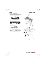
2. Immediately after removing the valve guides
from the freezer, insert the valve guides
(Figure 6-28, (1)) in their proper positions.
Figure 6-28
3. Finish installing the valve guides
(Figure 6-29, (1)) into the cylinder head to the
proper height (Figure 6-29, (3)) using the valve
guide installation tool (Figure 6-29, (2)). See
Valve Guide Projection specification starting on
page 6-7.
Figure 6-29
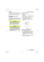
Reassembly of Intake and Exhaust Valves
IMPORTANT
Always install new valve stem seals.
The exhaust valve stem seals are different
than the intake valve stem seals and can be
identified by either the paint marks on the
outside of the seals or by the color of the
seal spring (Figure 6-30, (4)). Ensure they
are installed in the correct locations.
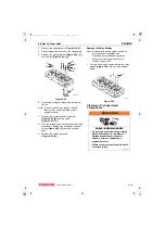
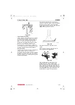
1. Oil the lip of the valve stem seal
(Figure 6-30, (2)). Using the valve stem seal
installation tool (Figure 6-30, (1)), install a new
valve stem seal on each of the valve guides
(Figure 6-30, (3)).
Figure 6-30
2. Measure the distance (Figure 6-31, (1)) from
the cylinder head to valve stem seal to ensure
proper clearance (Figure 6-31, (2)) between
the guide and the seal. See Valve Stem Seal
Projection specification on page 6-9.
(1)
001689
0001756A
(3)
(2)
(1)
Engine Model
Marking
Intake
Exhaust
3TNV84, 3TNV88,
3TNV84T, 4TNV84,
4TNV88
None
Yellow (Paint
on outside of
seal)
3TNV82A
None
Black (Seal
Spring)
(3)
(2)
(4)
(1)
0001873B
TNV_DI_SM_A4.book 45 ページ 2007年12月6日 木曜日 午前9時23分


