ENGINE
TNV DI Service Manual
6-61
4-Valve Cylinder Head
Reassembly of Cylinder Head
Use new gaskets, O-rings, and seals on
reassembly of the cylinder head.
IMPORTANT
Liberally oil all components during
reassembly to prevent premature wear or
damage.
Reassembly of Valve Guides
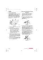
1. The valve guides are installed into the cylinder
head with an extremely tight press fit. Before
installing the valve guides, place the valve
guides in a freezer for at least twenty minutes
This will cause the valve guides to contract,
making it easier to install the valve guides into
place.
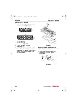
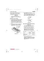
2. Immediately after removing the valve guides
from the freezer, insert the valve guides
(Figure 6-65, (1)) in their proper positions.
Figure 6-65
3. Finish installing the valve guides
(Figure 6-66, (1)) into the cylinder head to the
proper height (Figure 6-66, (3)) using the valve
guide installation tool (Figure 6-66, (2)). See
Intake / Exhaust Valve and Guide on page 6-7.
Figure 6-66
Reassembly of Intake and Exhaust Valves
IMPORTANT
When installing valve stem seals, use new
ones instead of reusing removed seals.
Exhaust valve and intake valve stem seals
are different. They can be distinguished
based on the paint marks on the outer side
of the seal or the color of the seal spring
(Figure 6-67, (4)). When installing each
stem seal, take care to correctly position it.
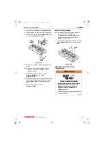
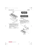
1. Oil the lip of the valve stem seal
(Figure 6-67, (2)). Using the valve stem seal
installation tool (Figure 6-67, (1)), install a new
valve stem seal on each of the valve guides
(Figure 6-67, (3)).
0001868
(1)
Engine Model
Marking
Intake
Exhaust
4TNV84
White (Seal
Spring)
Black (Seal
Spring)
4TNV94L,4TNV98,
4TNV98T,4TNV106,
4TNV106T
None
Black (Seal
Spring)
0001756A
(3)
(2)
(1)
TNV_DI_SM_A4.book 61 ページ 2007年12月6日 木曜日 午前9時23分


