STARTER MOTOR
11-16
TNV DI Service Manual
Starter Motor
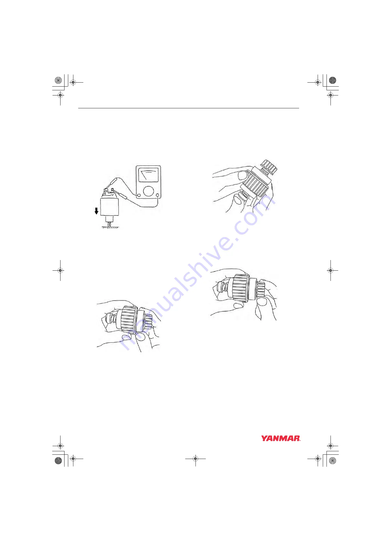
Contact Continuity Test
Depress the plunger at the bottom of the magnetic
switch. Check for continuity between the “B” and
“M” terminals using a multimeter (Figure 11-23).
The multimeter should indicate continuity.
If the multimeter does not indicate continuity,
replace the magnetic switch.
Figure 11-23
Pinion Clutch Assembly
Pinion Clutch Assembly Inspection
Manually rotate the pinion clutch assembly in the
drive direction (Figure 11-24). It should rotate
freely in the drive direction and is locked by turning
it in the opposite direction. Replace the pinion
clutch assembly if the results are different.
Figure 11-24
Slide the pinion clutch assembly on the shaft. It
should slide smoothly on the shaft (Figure 11-25).
Rust, too much grease or damage could prevent
the pinion clutch from sliding smoothly. If the pinion
clutch assembly does not slide smoothly, clean the
shaft and pinion clutch assembly or replace the
damaged component.
Figure 11-25
Ball Bearing Inspection
Rotate each ball bearing while holding the pinion
clutch assembly (Figure 11-26). Replace the ball
bearing if it does not rotate smoothly or has
excessive play.
Figure 11-26
0000126
0000127
0000128
0000129
TNV_DI_SM_A4.book 16 ページ 2007年12月6日 木曜日 午前9時23分


