ALTERNATOR
TNV DI Service Manual
12-15
Alternator
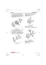
2. If removed, lubricate the outside diameter of a
new front frame housing bearing. Press the
bearing (Figure 12-13, (2)) into the front frame
housing. Reinstall the plate (Figure 12-13, (4))
to the front housing. Tighten the four bolts
(Figure 12-13, (3)).
Figure 12-13
3. Position the stator assembly (Figure 12-13, (1))
on the front frame housing studs.
4. Lubricate the shaft of the rotor assembly
(Figure 12-14, (1)). Press the rotor assembly
into the front frame housing (Figure 12-14, (2))
and rear frame housing (Figure 12-14, (3)).
Figure 12-14
5. Align the front frame housing with the rear
frame housing. Reinstall the two bolts
(Figure 12-15, (1)) and two nuts
(Figure 12-15, (2)).
Figure 12-15
6. Reinstall the insulation bushing
(Figure 12-16, (4)) and nut (Figure 12-16, (3)).
Figure 12-16
7. Reassemble the regulator assembly
(Figure 12-16, (1)) to the holder
(Figure 12-16, (2)).
1
2
4
3
0000259A
100266A
2
1
3
0000265A
1
2
3
4
1
2
0000258A
TNV_DI_SM_A4.book 15 ページ 2007年12月6日 木曜日 午前9時23分


