
ENGINE
6-24
3TNV88F Service Manual
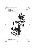
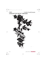
Cylinder Head
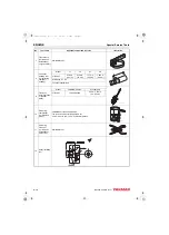
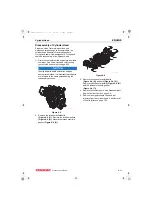
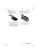
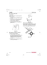
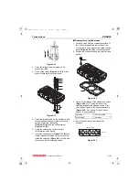
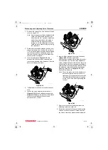
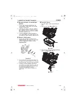
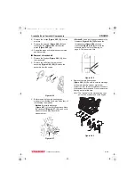
Valve recession
Note: The valve guides must be installed to
perform this check.
Insert the valves into their original locations and
press them down until they are fully seated. Use a
depth micrometer
difference between the cylinder head gasket
surface and the combustion surface of each
exhaust and intake valve
.
Cylinder Head on page 6-4 for the service limit.
Figure 6-21
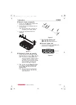
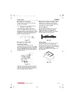
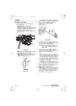
Figure 6-22
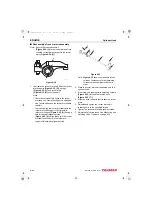
Valve face and valve seat
Always check the clearance between the valve and
valve guide before grinding or lapping the valve
seats.
See Intake/Exhaust Valve and Guide on
page 6-4 for the service limit.
If the clearance
exceeds the limit, replace the valve and/or valve
guide to bring the clearance within the limit.
Roughness or burrs will cause poor seating of a
valve. Visually inspect the seating surfaces of each
valve and valve seat to determine if lapping or
grinding is needed.
Visually inspect all valve faces and valve seats for
pitting, distortion, cracking, or evidence of
overheating. Usually the valves and the valve seats
can be lapped or ground to return them to
serviceable condition. Severely worn or damaged
components will require replacement.
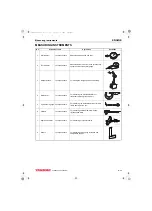
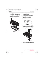
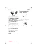
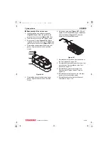
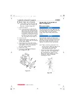
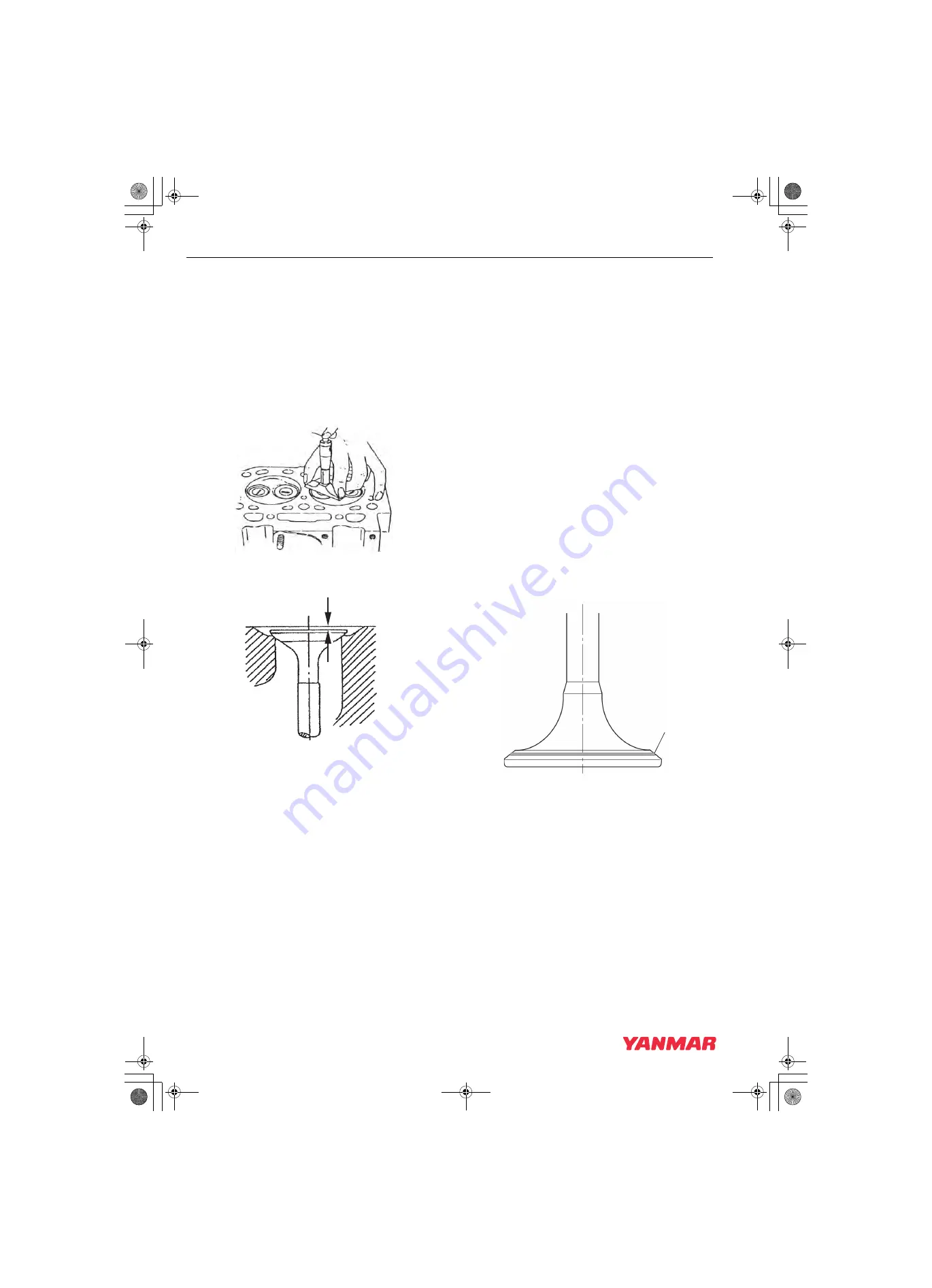
Coat the valve seat with a thin coat of bluing
compound. Install the valve and rotate it to
distribute bluing onto the valve face. The contact
pattern should be approximately centered on the
valve face
and even in width.
Figure 6-23
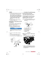
Also visually inspect the valve seat for even
contact.
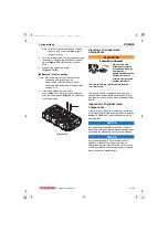
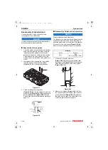
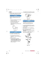
Light cutting can be performed by the use of a
hand-operated cutter
K0000193
K0001755
K0001691B
1
3TNV88F_SVM_A4.book 24 ページ 2012年7月26日 木曜日 午後6時4分


