
ENGINE
3TNV88F Service Manual
6-31
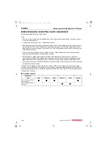
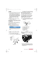
Measuring and Adjusting Valve Clearance
1. Remove the valve cover.
Note: If adjusting each cylinder individually, the
cylinder to be adjusted first does not
have to be the No. 1 cylinder. Select and
adjust the cylinder where the piston is
nearest to the top dead center after
turning, and make adjustment for other
cylinders in the order of firing by turning
the crankshaft.
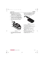
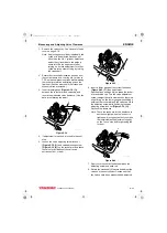
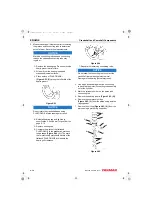
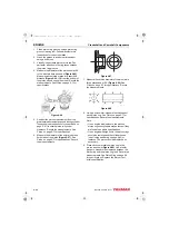
2. Rotate the crankshaft clockwise as seen from
the coolant pump end, to bring No. 1 piston to
TDC on the compression stroke while watching
the rocker arm motion and timing grid on the
flywheel. (Position where both the intake and
exhaust valves are closed.)
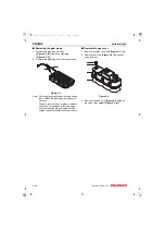
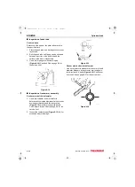
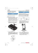
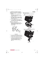
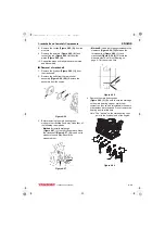
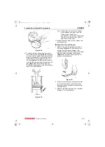
3. Insert a feeler gauge
between the rocker arm and valve cap, and
record the measured valve clearance. (Use the
data for estimating the wear.)
Figure 6-38
4. If adjustment is required, proceed to the next
step.
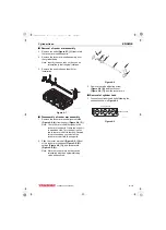
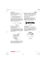
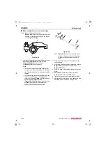
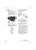
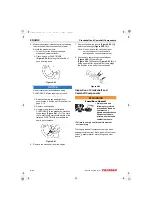
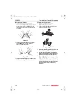
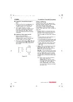
5. Loosen the valve adjusting screw lock nut
and valve adjusting screw
on the rocker arm and check
the valve for inclination of the valve cap,
entrance of dirt, or wear.
Figure 6-39
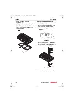
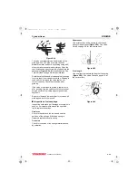
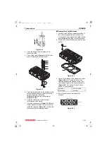
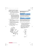
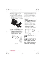
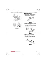
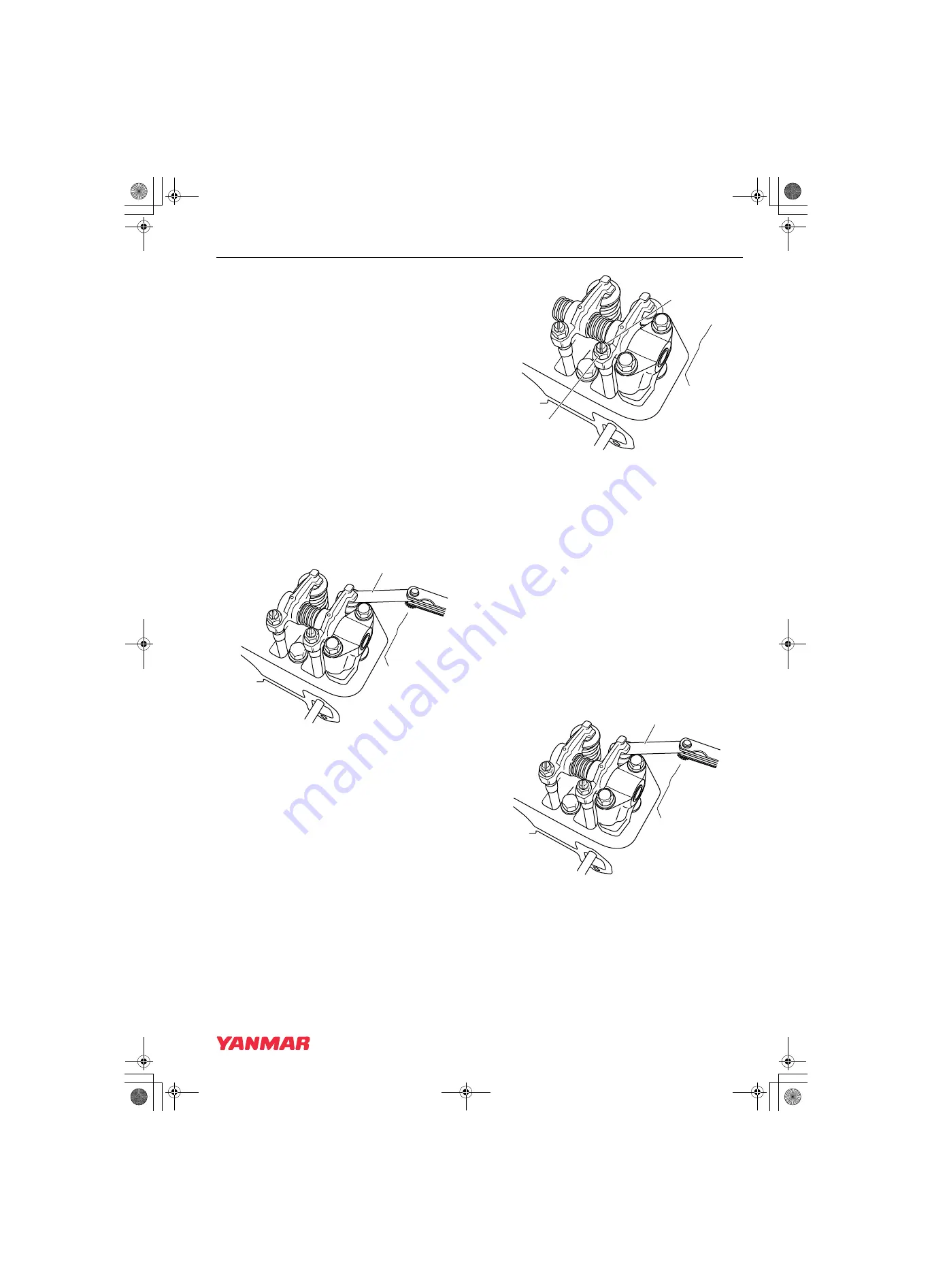
6. Insert a feeler gauge of the correct thickness
(Figure 6-40, (1))
between the rocker
arm and valve cap. Turn the valve adjustment
screw to adjust the valve clearance so there is a
slight “drag” on the feeler gauge when sliding it
between the rocker arm and the valve cap. Hold
the adjusting screw while tightening the valve
adjusting screw lock nut
(Figure 6-39, (1))
.
Recheck the clearance.
Note: There is a tendency for the clearance to
decrease slightly when the lock nut is
tightened. It is suggested that you make
the initial clearance adjustment slightly
on the “loose” side before tightening the
lock nut.
Figure 6-40
7. Apply oil to the contact surface between the
adjusting screw and push rod.
8. Rotate the crankshaft. Measure and adjust the
valves on the next cylinder. Continue until all
the valves have been measured and adjusted.
1
K0001782A
K0001783A
1
2
1
K0001782A
3TNV88F_SVM_A4.book 31 ページ 2012年7月26日 木曜日 午後6時4分


