ENGINE
6-60
3TNV88F Service Manual
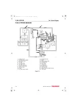
EGR system
Inspecting/Cleaning EGR Related
Components
■
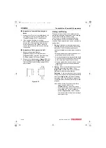
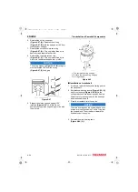
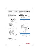
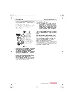
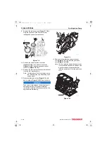
EGR valve
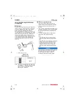
Each EGR valve has four built-in coils. The power
to each of the four coil is either ON or OFF at any
given time. Depending on which coil is ON and
which coil is OFF, the step motor rotates to
determine the valve lift. The power to each coil is
turned ON/OFF by the E-ECU based on the engine
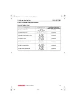
speed and fuel injection rate. The resistances of
these coils should be as specified below when
measured between each pair of pins shown. If any
of the actually measured values is beyond the
standard range, replace the entire EGR valve
assembly.
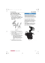
1 – EGR valve connectors
Figure 6-105
Standard value
Note: The higher the temperature, the higher the
coil resistance. Therefore, wait for the EGR
valve to return to normal state before
measuring the resistances.
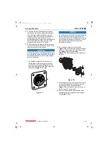
■
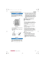
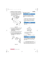
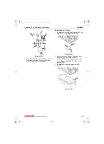
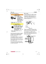
EGR valve operation checks
1. After removing each EGR valve from the
engine, connect the valve with the connector.
2. Connect the valve to the battery’s minus (-)
terminal.
3. Turn on the key switch.(Note that turning on the
key switch causes the E-ECU to check whether
the valve functions properly by opening and
shutting it.)
4. From the exhaust gas inlet, visually check
whether the valve operates correctly.
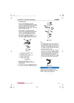
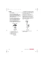
Note:
• If the EGR valve fails to smoothly operate,
replace the entire valve assembly with new
one.
• If the EGR valve does not respond at all, check
whether there exists a voltage (EGR valve
signal) between the connector pins. If the
voltage is within the standard range, then
replace the entire valve assembly with new
one.
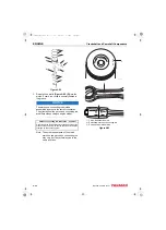
NOTICE
Alternatively, you can remove the EGR pipe from
the engine and check the valve operation
through the gas inlet window, instead of
removing the EGR valve from the engine.
Terminal
Resistance (
)
-
15 ± 2
at 20 °C
-
-
-
1
3TNV88F_SVM_A4.book 60 ページ 2012年7月26日 木曜日 午後6時4分


