
ENGINE
6-30
3TNV88F Service Manual
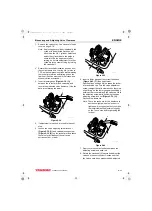
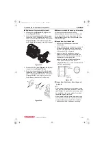
Measuring and Adjusting Valve Clearance
MEASURING AND ADJUSTING VALVE CLEARANCE
Measure and adjust while the engine is cold.
Note:
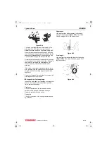
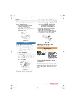
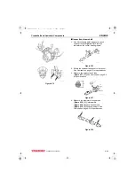
• The No. 1 piston position is on the flywheel end of the engine, opposite the radiator. The firing order is 1-
3-2 for 3-cylinder engines.
• 3-cylinder engines fire every 240° of crankshaft rotation.
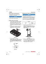
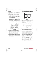
• Valve clearance of both the intake and exhaust valves can be checked with the piston for that cylinder at
top dead center (TDC) of the compression stroke. When a piston is at TDC of the compression stroke,
both rocker arms will be loose and the cylinder TDC mark on the flywheel will be visible in the timing port
of the flywheel housing.
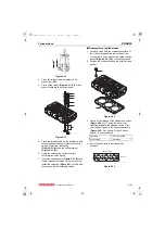
• If there is no valve clearance, and the cylinder is at TDC of the compression stroke, extreme wear, or
damage to the cylinder head or valves may be possible.
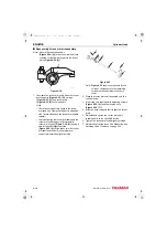
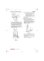
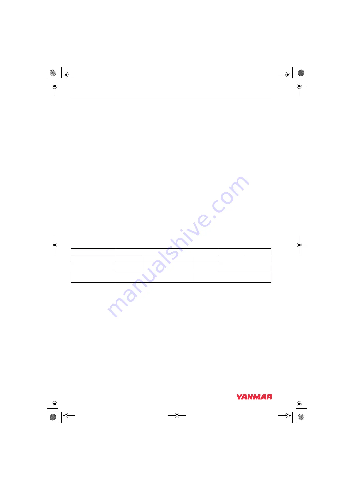
• If adjusting each cylinder individually, the cylinder to be adjusted first does not have to be the No. 1
cylinder. Select and adjust the cylinder where the piston is nearest to the top dead center after turning.
Make adjustment for the remaining cylinders in the order of firing by turning the crankshaft each time.
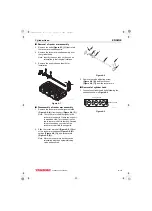
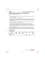
• To decrease the number of rotations required to check all cylinders, other cylinders can also be checked
as indicated in the chart below.
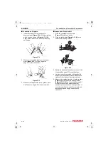
Example: On a 3-cylinder engine, with the No. 1 piston at TDC on the compression stroke (both valves
closed), the valves indicated on the top line of the chart can be adjusted without rotating the crankshaft. To
adjust the remaining two valves, rotate the crankshaft until the No. 1 piston is at TDC on the exhaust stroke
(exhaust valve only open).
■
3-cylinder engines
Cylinder No.
1
2
3
Valve
Intake
Exhaust
Intake
Exhaust
Intake
Exhaust
No. 1 cylinder at TDC
compression
No. 1 cylinder at TDC
exhaust
3TNV88F_SVM_A4.book 30 ページ 2012年7月26日 木曜日 午後6時4分


