
ENGINE
3TNV88F Service Manual
6-37
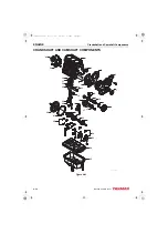
Crankshaft and Camshaft Components
■
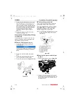
Removal of gear case or front plate
Note: The camshaft must be removed before the
gear case/front plate can be removed. See
Inspection of camshaft on page 6-45.
1. Remove the oil pump.
Note: It is not necessary to remove the fuel
injection pump from the gear case/front
plate to remove the gear case/front plate.
If the fuel injection pump does not need
to be repaired, leaving it mounted to the
timing gear case/front plate will eliminate
the need to re-time it during assembly.
See Fuel Injection Pump on page 7-11.
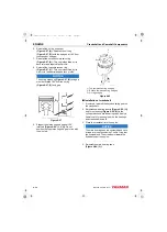
2. Remove the bolts.
3. Remove the gear case or front plate
from the
cylinder block. Thoroughly clean all old sealant
from the mating surfaces.
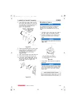
4. Inspect and measure the camshaft bushing.
See Camshaft on page 6-6 for the service limit.
If damaged or worn beyond service limits,
remove the camshaft bushing.
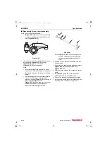
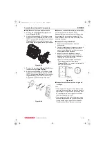
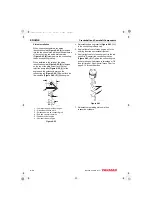
5. Remove two O-rings.
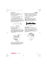
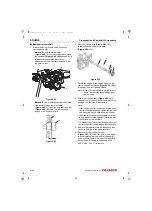
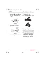
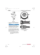
6. Remove the O-ring
(Figure 6-51, (2))
and
dowels
(Figure 6-51, (5))
.
Figure 6-51
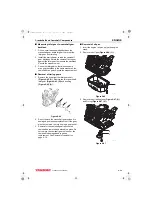
Disassembly of Crankshaft and
Piston Components
■
Removal of pistons
NOTICE
Keep the piston pin parts, piston assemblies, and
connecting rod assemblies together to be returned
to the same position during the reassembly
process. Label the parts using an appropriate
method.
NOTICE
Engines with high operating hours may have a
ridge near the top of the cylinders that will catch the
piston rings and make it impossible to remove the
pistons. Use a suitable ridge reamer to remove
ridges and carbon prior to removing the pistons.
Note: Pistons can fall from cylinder block if the
engine is inverted. Rotate the engine so the
connecting rods are horizontal before
removing the connecting rod caps.
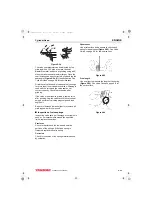
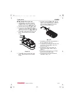
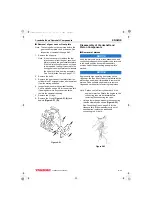
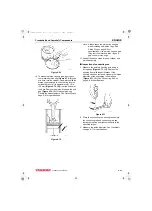
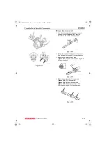
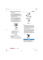
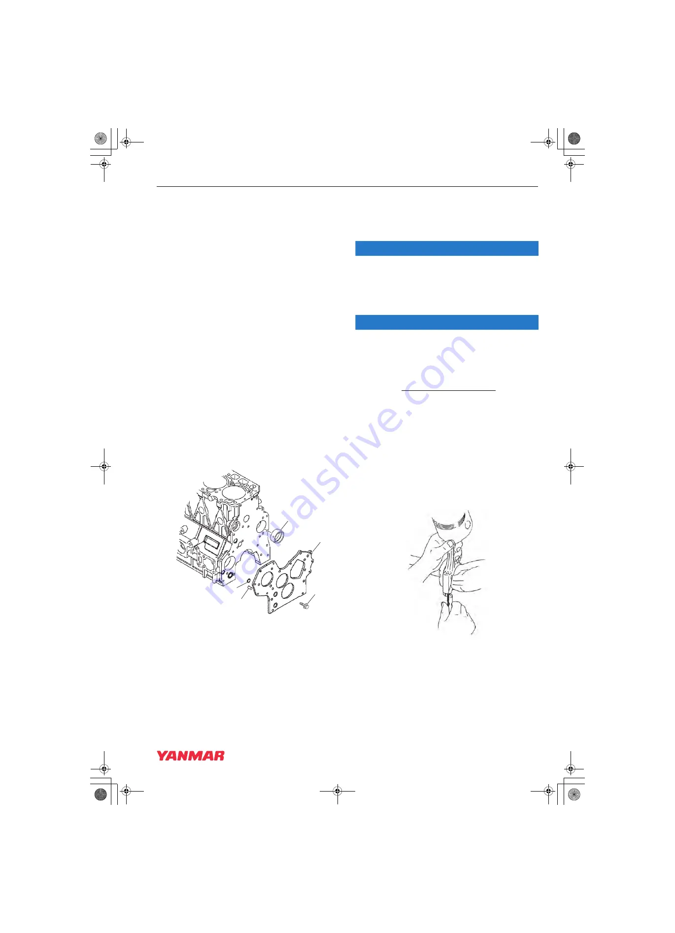
1. Using a feeler gauge, measure the connecting
rod side clearance as shown
See Connecting Rod on page 6-8 for the
standard limit.
If the measurement is out of
specification, replace the crankshaft,
connecting rod, or both.
Figure 6-52
K0002016
1
3
4
2
5
K0000219
3TNV88F_SVM_A4.book 37 ページ 2012年7月26日 木曜日 午後6時4分


