ENGINE
6-40
3TNV88F Service Manual
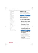
Crankshaft and Camshaft Components
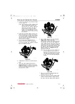
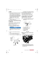
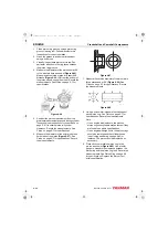
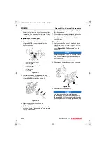
5. Measure bearing oil clearance prior to removing
the crankshaft to determine extent of wear.
Record the measurements.
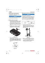
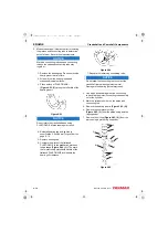
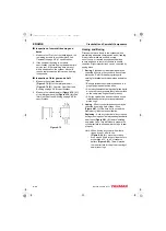
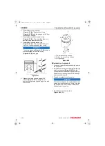
1- Wipe oil from the bearing insert and
crankshaft journal surfaces.
2- Place a piece of PLASTIGAGE
along the full width of
each bearing insert.
Figure 6-60
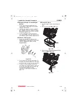
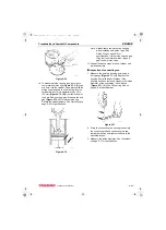
NOTICE
Do not rotate the crankshaft when using
PLASTIGAGE. A false reading may result.
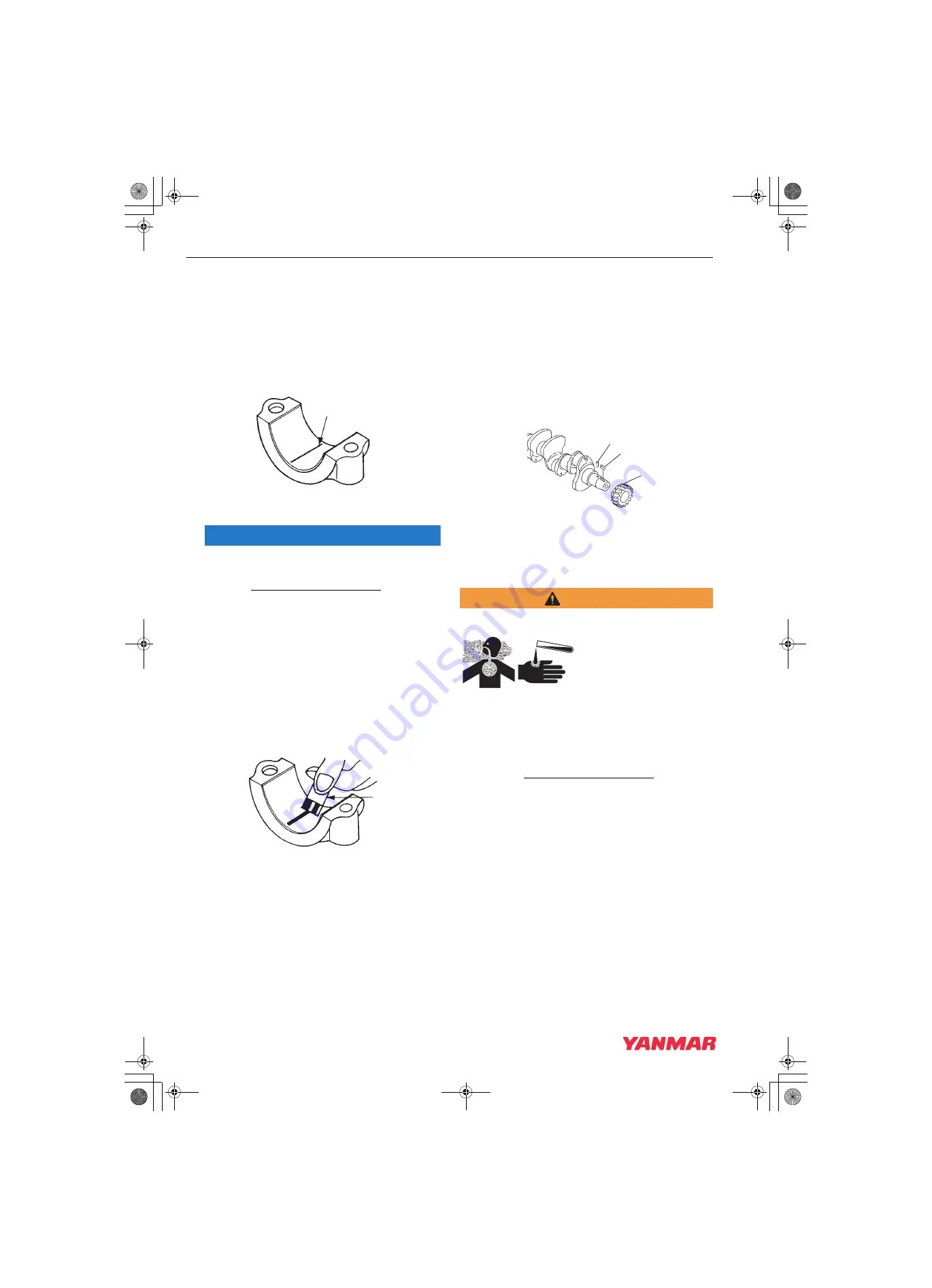
3- Reinstall bearing caps and tighten to
specification.
4- Remove bearing caps.
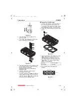
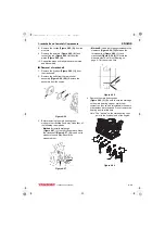
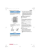
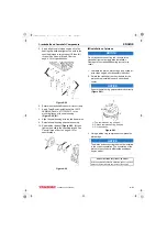
5- Compare the width of the flattened
PLASTIGAGE to the graduation marks on
the package
(Figure 6-61, (1))
. The mark
that most closely matches the width of the
flattened PLASTIGAGE will indicate the
bearing oil clearance.
Figure 6-61
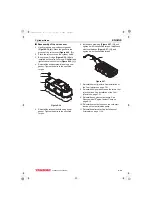
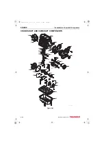
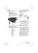
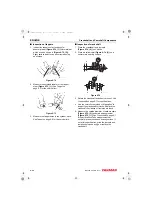
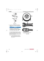
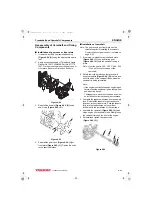
6. Remove the crankshaft from the engine.
7. Remove the bearing inserts
and thrust bearings
(Figure 6-59, (2))
.
Note: Do not remove the crankshaft gear
unless the gear or crankshaft are
damaged and require replacement.
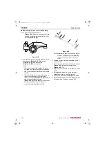
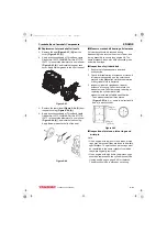
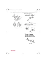
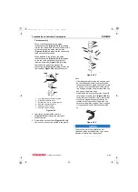
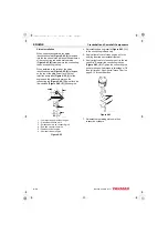
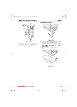
8. If necessary, remove the crankshaft gear
(Figure 6-62, (1)),
parallel pin
(Figure 6-62, (2))
and key
. If
using a gear puller, be careful not to damage
the threads in the end of the crankshaft.
Figure 6-62
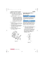
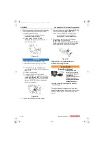
Inspection of Crankshaft and
Camshaft Components
WARNING
Fume/Burn Hazard!
• Always read and
follow safety related
precautions found on
containers of
hazardous substances
like parts cleaners,
primers, sealants and
sealant removers.
• Failure to comply could result in death or
serious injury.
Thoroughly clean all components using a brush
and appropriate solvent. Each part must be free of
carbon, gasket material, metal filings and other
debris.
K0001898
1
K0001899
1
K0001731A
1
2
3
3TNV88F_SVM_A4.book 40 ページ 2012年7月26日 木曜日 午後6時4分


