
ENGINE
3TNV88F Service Manual
6-49
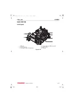
Crankshaft and Camshaft Components
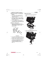
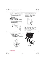
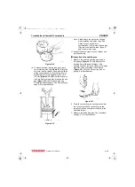
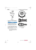
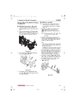
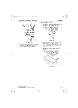
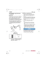
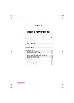
Piston assembly
When correctly assembled, the piston
identification mark
stamped
into the top of the piston will be on the same side
of the connecting rod as the match marks
stamped into the connecting
rod and connecting rod cap.
When installed in the cylinder, the piston
identification mark
stamped
on the top of the piston must face the fuel
injection pump side
of the
engine and the embossed mark on the
connecting rod
must face the
flywheel end
(Figure 6-84, (5))
of the engine.
1 – Fuel injection pump side of engine
2 – Piston identification mark
3 – Embossed mark on connecting rod
4 – Rod and cap match marks
5 – Flywheel end of engine
6 – Camshaft side of engine
Figure 6-84
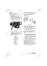
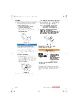
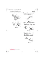
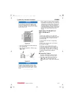
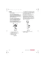
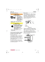
4. Lubricate and reinstall the wrist pin
through the piston and
connecting rod.
5. Reinstall the second circlip
and ensure it is securely seated in the groove.
Figure 6-85
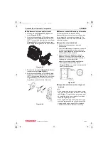
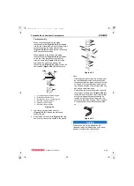
Note:
•
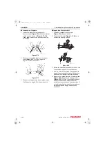
If installing new piston rings the end gap must
be checked and adjusted as necessary. See
Inspection of pistons, piston rings and wrist pin
on page 6-41 for specifications. Use a piston
ring end gap filing tool to adjust the piston ring
end gap on new piston rings.
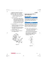
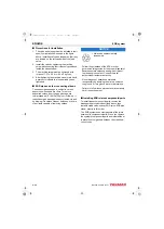
•
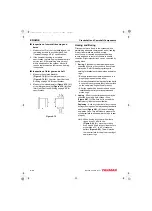
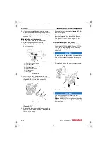
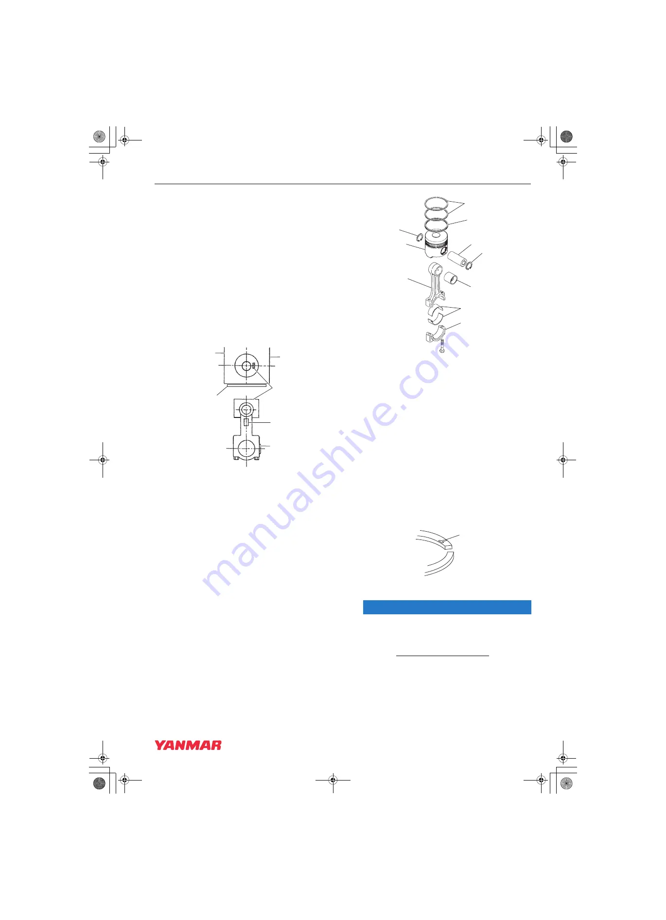
Reinstall the top and second piston rings with
the stamped “makers mark” (Figure 6-86 (1))
facing the top of the piston. The “makers mark”
may vary in appearance but will always be
located on the top surface of the piston ring
adjacent to the piston ring gap. The oil ring and
oil ring expander can be installed either side
up.
Figure 6-86
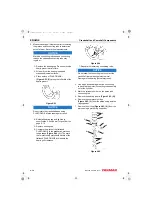
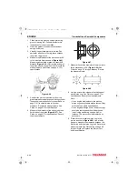
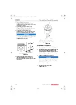
NOTICE
Always use a piston ring installation tool
(expander) when installing piston rings. Never
attempt to install piston rings by hand.
K0001967
1
6
5
3
2
4
3
4
5
9
6
8
7
5
2
1
K0001960
1
K0000225A
3TNV88F_SVM_A4.book 49 ページ 2012年7月26日 木曜日 午後6時4分


