FUEL SYSTEM
Fuel System Components
6-6
BY Service Manual
© 2009 Yanmar Marine International
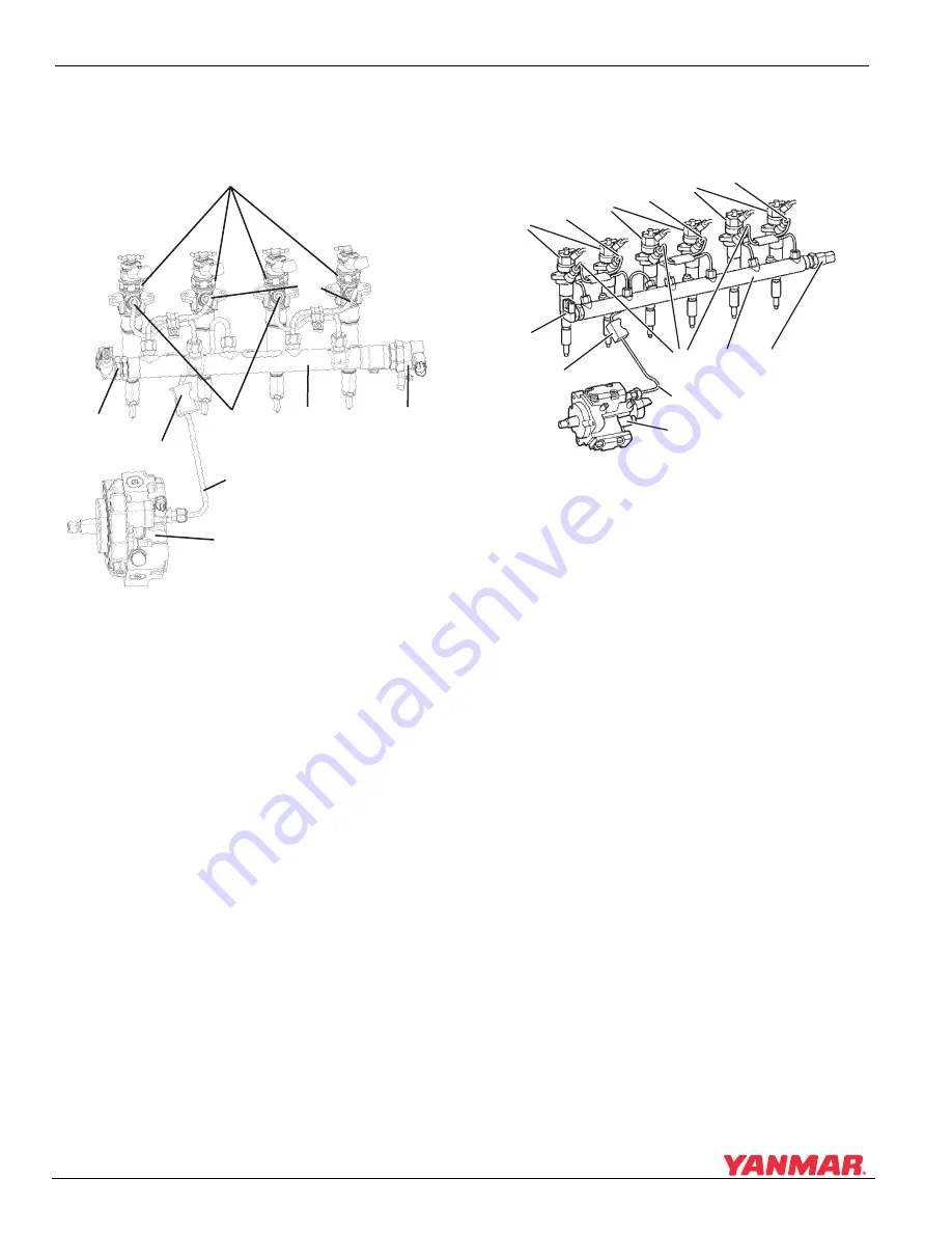
FUEL SYSTEM COMPONENTS
4BY2 Engines
Figure 6-1
Figure 6-1
1 – High-Pressure Line, Cylinders No. 1 and 3
2 – High-Pressure Line, Cylinders No. 2 and 4
3 – Fuel Injectors
4 – High-Pressure Fuel Rail
5 – High-Pressure Fuel Rail Pressure Sensor
6 – High-Pressure Line from Pump
7 – Rubber Insulator
8 – High-Pressure Pump with Fuel Measuring
Unit
9 – High-Pressure Fuel Regulator
6BY2 Engines
Figure 6-2
Figure 6-2
1 – High-Pressure Line, Cylinders No. 1, 3 and 5
2 – High-Pressure Line, Cylinders No. 2, 4 and 6
3 – Fuel Injectors
4 – High-Pressure Fuel Rail
5 – High-Pressure Fuel Regulator
6 – High-Pressure Line from Pump
7 – High-Pressure Pump with Fuel Measuring
Unit
8 – Rubber Insulator
9 – High-Pressure Fuel Rail Pressure Sensor
000654
9
(
3
)
(1)
(7)
(6)
(4)
(9)
(
8
)
(5)
(2)
000
3
675
(
3
)
(2)
(
3
)
(2)
(
3
)
(2)
(1)
(4)
(5)
(7)
(6)
(
8
)
(9)


