ELECTRICAL AND ECU
Function Description - Engine Management System
12/05
BY Service Manual
12-11
© 2009 Yanmar Marine International
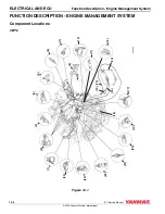
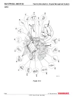
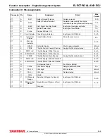
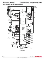
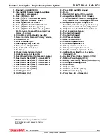
1 – Engine Control Unit (ECU)
2 – Internal ECU Sensors (operating voltage
and ambient air pressure)
3 – Fuse (F2) 10 A
1
- Start
4 – Fuse (F1) 3 A - CAN Switched Power
5 – Fuse (F6) 10 A - Auxiliary Power
6 – Start Signal from Key Switch
7 – Fuse (F4) 30 A - ECU Switched Power
8 – Fuse (F3) 15 A - Fuel Supply Pump
9 – Fuse (F5) 20 A - Fuel Pressure Regulator,
Water-in-Fuel, Camshaft Sensor, and Fuel
Volume Regulator
10 – Circuit Breaker (Boatbuilder Installed)
11 – Power to Starter Solenoid Primary Terminal
12 – Starter Relay K1
13 – Main Power Relay K2
14 – Fuel Supply Pump Relay K3
15 – Power to Fuel Supply Pump
16 – B+ to Water-in-Fuel Sensor
17 – Not Used
18 – Check Engine Indicator Output
19 – High-Pressure Fuel Regulator
20 – Fuel Volume Control (high-pressure pump)
21 – Fuel Injector No. 4 (4BY2) or No. 6 (6BY2)
22 – Fuel Injector No. 2 (4BY2) or No. 2 (6BY2)
23 – Fuel Injector No. 3 (4BY2) or No. 5 (6BY2)
24 – Fuel Injector No. 1 (4BY2) or No. 3 (6BY2)
25 – Fuel Injector No. 1 (6BY2)
26 – Fuel Injector No. 4 (6BY2)
27 – CAN Signal - Low
28 – CAN Signal - High
29 – Panel, ECU, and CAN Ground
30 – K-Line
31 – Neutral Start Switch (NC in neutral)
32 – Jumper Fuse (F8) 3 A - CAN / Analog
Throttle Selection, default is analog (fuse
out). Insert 3 A fuse to configure for CAN.
33 – Jumper Fuse (F7) 3 A - Single / Port
Selection, default is single / port (fuse in).
Remove fuse for starboard configuration.
34 – High-Pressure Fuel Rail Pressure Sensor
35 – Fuel Temperature Sensor
36 – Subthrottle Sensor 2
37 – Subthrottle Sensor 1
38 – Oil Pressure Sensor
39 – Water-in-Fuel Sensor
40 – Camshaft Speed Sensor
41 – Crankshaft Speed Sensor
42 – Charge Air Pressure Sensor
43 – Charge Air Temperature Sensor
44 – Engine Coolant Temperature Sensor
45 – Ignition Power Input from Key Switch
(terminal X1-D)
46 – Auxiliary Power Output (terminal X1-G)
47 – NMEA + Power Supply (X7-R)
48 – Battery Power to Key Switch (terminal X1-B)
49 – CAN Signal Blocking Diode
50 – High Bench 1
51 – High Bench 2
52 – Oil Pressure Switch (X1-Q)
53 – NMEA Ground Supply
54 – Power Resistor for Generator
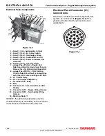
1
NEVER connect any additional devices to
F2. F6 may be used however, it is not
switched.

