background image

IMPORTANT NOTE: 

REMEMBER ALWAYS TO CONNECT 

FORWARD PAINTER LINE 

TO MOTHER VESSEL, 

BEFORE LAUNCHING THE BOAT. 

WHEN YOU ORDER SPARE PARTS, 

OR HAVE ANY QUESTIONS, 

PLEASE CONTACT: 

Supplier: 

MARITIME PARTNER 

Postboks 776, Sentrum 

6001 AALESUND, NORWAY 

Telefon: +47 70 11 65 65 Telefax: +47 70 11 65 55  

E-mail: office@maritime-partner.com  

www.maritime-partner.com 

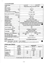
Summary of Contents for 4LHA-DTP

Page 1: ...R VESSEL BEFORE LAUNCHING THE BOAT WHEN YOU ORDER SPARE PARTS OR HAVE ANY QUESTIONS PLEASE CONTACT Supplier MARITIME PARTNER Postboks 776 Sentrum 6001 AALESUND NORWAY Telefon 47 70 11 65 65 Telefax 47 70 11 65 55 E mail office maritime partner com www maritime partner com ...

Page 2: ...Content Section Description Doc no Rev VOLUME 2 5 Operation User Instructions Continue Engine Yanmar 4LHA STP Operation Manual Parts Catalog Service Manual maritime partner as ...

Page 3: ...ERATION MANUAL YANMAR YANMAR DIESEL ENGINE 4 L H A H T P H T Z P 4 L H A D T P D T Z P 4 L H A S T P S T Z P Be sure to read this manual for safe and proper operation Store this manual carefully after use ...

Page 4: ...ditions should you have any questions or concerns please do not hesitate to contact your nearest dealer California Proposition 6 5 ming Diesel engine exhaust and some of its constitutions are known to the State of California to cause cancer birth defects and other reproductive harm California Proposition 65 Warning T 4 4 r r o f A v m t n a l c L J m i J j and related accessories contain lead and ...

Page 5: ... access i f this Operation Manual is lost or damaged order a new one from your dealer or distributor M a k e sure this manual is transfered to subsequent owners This manual should be considered a permanent part of the engin and remain it C o n s t a n t efforts are made to improve the quality and performance of Yanmar products so some details included in this Operation Manual may differ slightly f...

Page 6: ...ine lube oil 27 3 4 Supplying Marine Drive oil 2 8 3 5 Supplying Cooling Water 29 30 o e o 1 3 0 o v s w i c i i i c x i i i y 3 7 Checking the Lube Oil and Cooling Water 3 1 4 HOW TO OPERATE 32 4 1 Inspection Before Starting Z2 m 4 2 Checking the Control Panel and Alarm Devices 3 4 4 3 Starting 3 4 3 5 4 3 1 Daily Starting 34 4 3 2 Starting Under Low Temperature Conditions 3 4 4 3 3 Restarting Af...

Page 7: ...Operation 44 5 2 2 Inspection Every 50Hours 4 5 4 7 5 2 3 Inspection Every 250 Hrs orl yr 4 8 5 1 5 2 4 Inspection Every 500 Hrs or2 yrs 52 5 2 5 Inspection Every 1000 Hrs or 4 yrs 52 53 5 2 6 Inspection Every 2000Hrs 4 S 3 5 4 6 TROUBLE AND TROUBLESHOOTING 5 5 56 7 SYSTEM DIAGRAMS s 7 6 3 7 1 Piping Diagram 57 60 7 2 Wiring Diagram 6 1 6 3 3 ...

Page 8: ...n the products Pay special attention to them A DANGER DANGER indicates an imminently hazardous situation which if not avoided WILL result in death or serious injury A WARNING WARNING Indicates a potentially hazardous situation which if not avoided COULD result in death or serious injury mm situation which if not avoided MAY result in minor or moderate injury It may also be used to alert against un...

Page 9: ...t in ignition Be sure to stop the engine before refueling If you spill fuel wipe such spillage carefully Never place oils or other flammable material close to the engine as this could result in ignition A WARNING Exhaust Gas Poisoning Be sure to establish good ventilation in the engine room with windows vents or other ventilation equipment Check again during operation to be sure that venti lation ...

Page 10: ... it If you must inspect while the engine is operating never touch moving parts Keep your body and clothing well clear of all moving parts as this could result in injury Precautions for Removing Hot Oil and Water to Prevent Burns If extracting oil from the engine while it is still hot do not let the oil splash on you W wan unm tne lemperaiure nas aropptsu utsiuio IOIMOVHI engine to avoid getting sc...

Page 11: ... labels when parts are replaced ordering them in the same way as the parts Warning device labels Parts numbers No Part Code No D 128296 07300 D 120324 07240 D 128296 07260 128296 07350 P Ik I L 1 A flfr Kflfr V Jl ff i N j Ull l A j j Name plate D Araæ DANGER Never remove the cap while the engine is till hot Hot water may spurt out and burn you 128296 07260 A Jo Bl DANGER n o 2 Bra s tras When lif...

Page 12: ... A g g WARNING E x p o s e d moving parts C a n c a u s e injury 128296 07360 D CAUTION Hot surface May cause burn 1 28296 07 300 8 ...

Page 13: ...other onboard equipment be sure to observe the instructions and cautions given in the operation manuals supplied by the shipyard and equipment manufacturers The laws of some countries may require hull and engine inspections depending on the use size and cruising area of the boat The installation fitting and surveying of this engine all require specialized knowledge and engineering skills Consult Y...

Page 14: ...ywheel side Lube oil capacity All 13 0 Oil pan 10 0 Cooling water capacity 15 Engine 0 8 Sub tank Turbochager Model RHC61W IHI made Type Water cooled turbine housing Dimension L XW XH gear less mm 937X681X741 1039 X777 X830 Dry mass tgear lésSj Recommended battery capacity Recommended type of remote control handle 388 12VX120Ah Single lever type only Engine installation style On the flexible engin...

Page 15: ...el RHC61W IHI made Turbochager Type Water cooled turbine housing Dimension LXWXH gear less mm 937X686X741 1039X787X830 Dry mass gear less kg 365 388 Recommended battery capacity 12VX120Ah Recommended type of remote control handle Single lever type only Engine installation style On the flexible engine mount I Note 1 Rating condition ISO 3046 1 2 1 hp 0 7355 kW 3 Fuel condition Density at 15 C 0 860...

Page 16: ...s gear less kg 365 385 Recommended battery capacity 12VX120Ah Recommended type of remote control handle Oivx wlo M Ar H r t a r r l yiv w r Engine installation style On the flexible engine mount Note 1 Rating condition ISO 3046 1 2 1 hp 0 7355 kW 3 Fuel condition Density at 150 C 0 860 Fuel oil temperature 2 5 at the fuei injection pump inlet Marine gear Option Model HURTH HSW630A1 MERCRUSER Model...

Page 17: ...2 3 Names of parts Inter Cooler Fuel injection valve Fuel oil filter Lube oil fiiter Fuel injection pump Alternator Note This illustration shows the 4LHA HTP engine 13 ...

Page 18: ...e oil cooler Fuel oil filter Fuel injection pump Lube oil filter Fresh wal Alternator er cooler Turbo charger Exhaust manifold cooler Cooling fresh water pump Sea water pump Starter moter Note This illustration shows the 4LHA DTP er Be 1 4 ...

Page 19: ...Cooler Fuel injection valve Stern driving devices B R A V O MERCRUISER Fuel oil filter Fuel injection pump Turbocharger Mixing elbow AHemator Exhaust tube Note This illustration shows the 4LHA HTZP engine 1 5 ...

Page 20: ... OSub tank ORubber hose Fresh water pump Seawater pump The fresh water cooler is a heat exchanger using sea water wSen L engine stops and cooling water cools the pressure hthe c a w a w tank aiso dro s to n e g a t i v e Z S S S back from tne suo xan i ms nun Coolina Water System Fresh water cooler OFiller cap OSub tank ORubber hose Fresh water pump Seawater pump The centrifugal water pump circula...

Page 21: ...ngine stop switch 10 Switch unit Alarm buzzer 9 Switch unit Alarm buzzer stop switch 11 Switch unit Illumination switch for meters 6 Alarm lamp unit Battery not charging 6 Alarm lamp unit C W high temperature 6 Alarm lamp unit L O low pressure engine 6 Alarm lamp unit C W level 6 Alarm lamp unit Exhaust 6 Alarm lamp unit Boost 6 Alarm lamp unit Fuel filter 6 Alarm lamp unit Gear oil stern drive 1 ...

Page 22: ... temperature o Switches L 0 low pressure o Switches C W level X Switches Exhaust C S Wflow X Switches Boost X X X X A A Switches Gear oil Stern X A X A X A Switches Fuel filter O o X X X X Senders Tachometer O Senders C W temperature A Senders LO pressure A Senders Boost A Senders C W temp For two stations A Senders L O press For two stations A O Standard A Optional X Not available 1 8 ...

Page 23: ...er The buzzer sounds if an abnormality arises See explanation under 2 Warning lamps The lamps come on when an abnormality arises See explanation under 2 Buzzer stop switch The switch is used to stop the buzzer noise temporarily Do not turn the buzzer off except when inspecting for an abnormality illumination switch Switch for lighting control panel Hour meter Total operation hours are shown in the...

Page 24: ...on when the drain in the water separator located bottom of the fuel filter becomes excessive Clean out the drain in the water separator Gear Oil Level In The Stern Drive Warning Lamp The lamp comes on when the gear oil level in the stern drive falls below the specified level Check the amount of gear oil in the stern drive Boost Pressure Warning Lamp The lamp comes on when the intake air boost pres...

Page 25: ...ote control cable with the remote control handle in the cockpit There are the following kinds of remote control handles When using other kinds of remote control devices consult their operation manuals Morse Remote Control Handle Optional This is a single handle control device connected by a remote control cable It operates the clutch k to neutral forward and reverse and controls the engine speed M...

Page 26: ... to full speed Free throttle operation When the boat is stopped clutch is in neutral position the idling speed of the engine can be increased in the following manner Leave the handle lever in NEUTRAL V h S l w MT 3 Pull out the handle lever all the way MV Pull out the free throttle button next to the handle lever DWith the lever or button pulled out move the handle lever in either the forward or r...

Page 27: ...s so that water and dust in ihe fuei are deposiied on ihe bottom Pump up only the clean fuel 3 Use fuel with a Cetane number of over 45 4 When supplying fuel to a new boat for the first time be sure to extract all fuel from the F O tank and check for impurities in the fuel Pump up only fuel above the down half leaving dreg accumulated on the bottom 3 Fuei piping Install the piping between the fuel...

Page 28: ... T 7 P D T Z P S T Z P System OH Drive oil t power steering oil Power trim oil Specified lube oil Quicksilver High Performance Gear Lube Quicksilver Power Trim and Steering Fluid or Dexione I Quicksilver Power Trim and Steering Fluid or SAE 10W 30 or 10W 40 engine oil For further more instructions refer to the maker s manual Follow the maker s instructions for the marine gears HSW450A2 HURTH 4LHA ...

Page 29: ...ooling water system periodically according to the instructions this operation manual 5 Strictly use the proper mixing ratio of LLC to fresh water as instructed by the LLC maker If incorrect ratio of LLC to fresh water is used the cooling performance of the cooling water will drop and the engine may become overheated 6 Do not mix different types brand of LLC chemical reactions may make the LLC usel...

Page 30: ...ystem according to the following procedure When there s a r the fuel injection pump will not be able to function i 4LHA DTP DTZP STP STZP Open the cock on the fuel oil inlet pipe line and loosen the air bleeding bolt on the top of the water fuel oil separator optional by When fuel turniny o un with no air bubbles came out tighten the air bleeding bolt Loosen the priming pump knob turning counter c...

Page 31: ... tighten the air bleeding screw Air bleeding screw F O priming pump knob F O feed pump 3 3 Supplying Engine Li 8 ISSBifci Fill with the specified amount of engine oil Remove the fiiier cap on the top of ihe bonnei and fill with oil Remove the oil dipstick and supply lube oil to the upper limit on the oil dipstick To check the oil level insert the dipstick in fully Engine oil capacity ALL 13 i Oil ...

Page 32: ...vice BRAVO there is the power steering oil service tank on the engine side Fill with the specified amount of the power steering oil 4LHA HTZP DTZP STZP DRemove the cap from the power steering oil service tank by turning it to the right and supply the power steering oil Fill with the oil to the upper limit marked on the dipstick attached to the inside of the cap To check the oil level wipe the dips...

Page 33: ...he filler cap of the fresh water tank Turn the filler cap by 1 3 turn counter clockwise to remove Supply cooling water slowly to the fresh water tank so that no air bubbles will develop Supply until the water overflows from the filler port After supplying cooling water fasten the filler cap firmly If loose trouble will occur due to water leakage To fasten align the notch at the back of the cap wit...

Page 34: ...e may result in engine seizure since there will no longer be oil on the moving parts after storage Open kingston cock optional Put marine drive in NEUTRAL v 1 i v S N r r O J l_ fCU irv ti i c o i l y n i w Push the stop button to stop fuel cut while cranking 1 Put the key into the starter switch 2 While pushing the stop button turn the key to the START position and hold it there The engine will b...

Page 35: ... have been replaced their levels should be checked after a trial operation Oil and water will be distributed to the various parts during the operation lowering the levels of oil and water Replenish to the proper amounts Supplying engine lube oil See 3 3 Supplying marine drive oil See 3 4 Supplying cooling water See 3 5 31 ...

Page 36: ...AUTION Burns from Contact with Hot Engine Parts The whole engine is hot during operation and immediately after stop ping The turbocharger exhaust manifold exhaust pipe and engine are very hot Never touch these parts with your body or clothing ST 4 1 Inspection Before Starting w Wm WBr Be sure to check the following items daily before starting the engine 1 Visual Check Check for the following If an...

Page 37: ...ng the water level while the engine is hot is dangerous and the cooling water level reading will be misleading due to thermal expansion Check the cooling water daily at the subtank and supply ifnecessary Do not remove the fresh water tank filler cap regularly The amount of water in tne subtank wiii increase auring operation This is normal When the engine is stopped the temperature of the cooling w...

Page 38: ...nt is working properly Turn the key to START to start the engine When the engine has started remove your hand from tne key The key wiii automat ically return to the ON position Check to see that alarm lamps have gone off and the buzzer has stopped MT 3 MV Remove hand after S engine starts Drive position START GLOW Start position 4 3 2 Starting Under Low Temperature Conditions When starting the eng...

Page 39: ... Leave the remote control handle in NEUTRAL Pull out the handle lever MT 3 or the free throttle button MV and adjust the speed to no more than 1500rpm and run the engine at low speed with no load r NOTICE The engine will seize if it is operated when cooling seawater discharge is too small or if load is applied without any warming up operation MT 3 MV NEUTRAL 1 fW JDthrottle button Pull out handle ...

Page 40: ...5 1 Forward Neutral Reverse K CUTOA Use the remote control handle to operate the clutch for the marine drive FORWARD NEU1HAL REVERSE Use a single lever type remote control handle Return the handle to NEUTRAL before mov ing it to another position securely Always move the handle smoothly never change positions abruptly Be sure to securely position the handle in FORWARD NEUTRAL or REVERSE Morse Remot...

Page 41: ...ion lower the engine speed immediately check the alarm lamps and stop the engine for repairs 5 Is there water oil or gas leakage or are there any loose bolts Check the engine room periodically for any problems 6 Is there sufficient oil in the fuel tank Replenish fuel oil in advance to avoid running out of fuel during operation 7 When operating the engine at low speed for long periods of time race ...

Page 42: ...n the starter switch to OFF remove the key and place it in a safe place Turn off the battery switch Close the fuel tank cock Close the kingston cock NOTICE Stopping the engine suddenly after operating at high speed without cool ing it down will cause the engine tem perature to rise quickly resulting in deterioration of the lube oil and stick ing of parts In the rare instance where the engine does ...

Page 43: ... t Checking the Alarm Devices Tum the key for no longer than 15 sees Remove hand from key after starting Checking for Problems Low Speed Position 1 SOOrpm or lower for 5 mins or longer Checking the Engine Dunng Operation I Starting Operation I Marine Drive Clutch Speed Lever Engage Clutch Forward or Reverse Adjust Speed Stopping the Boat Prepanng to Stop the Engine I Speed Lever r Marine Drive Clu...

Page 44: ...water systems r NOTICE If the water is not drained it may freeze and damage parts of the cooling water system I Draining the water from the seawater system Open the water drain cock on the seawater side of the fresh water cooler and drain off the cooling seawater Open the water drain cock on the oil cooler and intercooler and drain off the cooling seawater Open the cock on the marine gear follow t...

Page 45: ...To prevent condensation inside the fuel tank either drain off the fuel or fill the tank Grease the exposed area and joints of the remote control cable and the bearings of the remote control handle Cover the intake silencer exhaust pipe etc with vinyl sheets and seal them to prevent moisture from entering 1 Drain bilge in the hull bottom completely Water may leak into the boat when it is moored and...

Page 46: ...s for consumable and replacement parts Use of other parts will reduce engine performance and shorten the life of the engine Servicing Tools Prepare servicing tools onboard to be ready for inspecting and servicing the engine and other equipments Tightening Torque of Nuts Bolts Over tightening of bolts and nuts causes them to come off or their threads to be damagecL Insufficient tightening causes oi...

Page 47: ...e lube oil filter element First Lube oil Wash engine oil cooler Drive oil Check the quantity of drive oil o Refer to operation manual of marine drive Drive oil Replace drive oil Refer to operation manual of marine drive Drive oil Check power trim oil o Refer to operation manual of marine drive Drive oil Check power steering oil o marine gear oil For informations marine gears refer to the maker s m...

Page 48: ...de 2 Drain off the oil with the drain pump 3 Remove the drain plug at the bottom of the engine oil cooler and drain off the oil inside Replace the lube oil filter 1 Turn the iube oii fiiter to the iefi using ihe filter wrench and remove 2 Clean the filter installation face 3 Apply engine oil to the installation face and lightly screw in the filter in position and tighten it unitl the gasket comes ...

Page 49: ...and dirt have been drained off and the fuel coming out is clear close the drain cock To engine Settling tank Drain cock Drain cock 2 Draining the Oil Water Separator Optional Close the fuel cock Loosen the plug screw at the bottom of the oil water separator and drain water and dust from inside After draing of the oil water separator be sure to vent air from the fuel system 4LHA DTP DTZP STP STZP A...

Page 50: ...e drain plug at the bottom of the fuel filter and drain off any water and dirt collected inside Retighten the drain plug Be sure to bleed air out of the fuel system See 3 2 2 a Fuel filter Drain cock Fuel filter Drain plug 4 Inspection of Battery AWARNING Fire due to Electric Short Circuits Always turn off the battery switch or detach the earth cable before inspecting the electrical system Failure...

Page 51: ... earlier than the specified times If the engine cranking speed is so slow that the engine does not start up recharge the battery If the engine still will not start after charging replace the battery Local supply Upper Level Lower Level Battery Fluid Follow the instructions and precautions in the manual from the battery maker NOTICE The capacity of the specified alternator and battery is sufficient...

Page 52: ...ly tighten the filter by a 3 4 turn tightening torque 14 7 19 6 N m 1 5 2 0 kgf m Connect the alarm switch wiring Fill fuel to the fuel filter see 3 2 2 If you spill fuel wipe such spillage carefully Start the engine to check for fuel leakage 2 4LHA DTP DTZP STP STZP Replace the fuel filter element periodically before there is clogging and the fuel flow is reduced Ciose the fuei cock of the fuei t...

Page 53: ... zinc is on the following parts NOTICE If replacement of zinc is neglected and operation is continued with a small volume of anti corrosive zinc corrosion of the seawater cooling system will occur and water leak age parts breakage or accidents will result Part Parts No Quantity Dimensions DXL Intercooler 119574 18790 1 V2 XV Engine oil cooler 119574 44150 2 U2 XV Fresh water cooler 119574 44150 2 ...

Page 54: ... make contact with stopper adjust as follows Remove the threaded area and the con necting pivot of the remote control cable from the governor lever Adjust the cable stroke by adjusting the fastening distance of the threaded area Loosen the setting bolt of the remote control cable clamp bracket and adjust the fixing position of the remote control cable However the adjustment of the remote control c...

Page 55: ...precleaner If the precleaner is excessively dirty wash with detergent and dry before reattaching If the precleaner is damaged replace it If there is still no improvement consult your local Yanmar dealer r NOTICEj Do not pour in a large amount of blower wash at one time pour it in gradually as this can damage the blower blades and get water hammer in the combustion chamber leading to accidents Blow...

Page 56: ... enough tension in the V belt the oil pump will not turn making steering impossible and operation dangerous Check the tension of the V belt in the following manner Press the V belt down with your thumb at the middle of the belt to check the tension The give in the V be t should measure about 8 10mm at the depression To adjust the V belt tension loosen the set bolt and move the oil pump Replace the...

Page 57: ...n pipe beneath the seawater pump during operation disassembly and maintenance replacement of the oil seal is necessary NOTICE The seawater pump revolves clockwise but the impeller blades must be installed in the counterclockwise direction During reassembly be sure to install the impeller blades correctly shown in the illustration right When turning the engine manually never turn it in the reverse ...

Page 58: ...s maintenance requires specialized knowledge Consult your Yanmar dealer or distributor 3 Inspection and Adjustment of Fuel Injection Timing Fuel injection timing must be adjusted to ensure optimal engine performance This maintenance requires specialized knowledge Consult your Yanmar dealer or distributor 5 4 ...

Page 59: ...k resupply replace Replace LO filter Replace Eng L O Check the oil level and supply Check C W level resupply System clogged air has entered the system Ask for repairs Drain the water in the W O separator of the fuel filter 3 3 5 2 1 1 5 2 1 1 3 4 3 5 5 2 2 3 f Warning Devices are Faulty When Switch is Turned ON OAlarm buzzer does not sound OWarning lamps do not go on Eng L O Press OCharge lamp doe...

Page 60: ...rts seized broken Load increased Turbocharger blower contaminated Fuel improper Faulty spraying by F O injection valve lnt exh valve head clearance excessive Improper fuel Faulty spraying by F O injection valve F O injection timing lags Lube oil burns excessive consumption Measure Reference Replace V belt adjust 5 2 4 1 tension Check fluid level specific gravity replace 5 2 2 4 Ask for repairs Res...

Page 61: ...E FUEL INJECTION PUMP OIL PRESSURE SENDER OIL PRESSURE SWITCH OIL PRESSURE LUB OIL FILTER WATER TEMP SWITCH COOLING FRESH WATER PUMP TO WATER HEATER THERMOSTAT WATER TEMP SENDER t 8 DETAIL OF PART SCALE 1 1 COOLING SEAWATER PUMP COOLING SEA WATER INLET 3 3 8 8 tk r x FUEL INJECTION NOZZLE INTER COOLER TO WATER HEATER MARINE GEAR and OIL COOLER COOLING SEA WATER OUTLET TURBOCHARGER FRESH WATER COOL...

Page 62: ...RESSURE PIPE OIL PRESSURE SENDER OIL PRESSURE SWITCH LUB OIL FILTER LUB OIL COOLER FROM WATER HEATER WATER TEMP SWITCH COOLING FRESH WATER PUMP TO WATER HEATER THERMOSTAT WATER TEMP SENDER COOLING SEAWATER PUMP DETAIL OF PART COOLING SEAWATER INLET SCALE 1 1 SJ S FUEL INJECTION NOZZLE POWER STEERING CYLINDER Local supply INTER COOLER TO WATER HEATER POWER STEERING OIL COOLER COOLING SEAWATER OUTLE...

Page 63: ...VE FROM WATER HEATER WATER TEMP SWITCH COOLING FRESH WATER PUMP HO Q1 TO WATER HEATER THERMOSTAT WATER TEMP SENDER OIL PUMP SUB DETAIL OF PAR COOLING SEA WATER PUMP CAMSHAFT BEARING MAIN BEARING COOLING SEA WATER INLET From F O NOZZLE FUEL OUTLET JOINT 1 1 1 1 8 il c 3 i ill ROCKER SHAFT FRESH WATER COOLER COOLING NOZZLE OF PISTON OIL INLET FILTER s MARINE GEAR AND W _ O I L COOLER COOLING SEA WAT...

Page 64: ...FILTER LUB OIL COOLER OIL PUMP SAFETY VALVE FROM WATER HEATER WATER TEMP SWITCH COOLING FRESH WATER PUMP TO WATER HEATER DETAIL OF PAR From F O NOZZLE From F O PUMP THERMOSTAT WATER TEMP SENDER OIL PUMP SUB COOLING SEA WATER PUMP COOLING SEA WATER INLET FUEL OUTLET JOINT DETAIL OF PAH DETAIL OF PAR DETAIL OF PAR FUEL INJECTION NOZZLE POWER STEERING CYLINDER Local supply INTER COOLER TO WATER HEATE...

Page 65: ...1 2 3 Sm AOmm2 Cross sectional area 12V I Battery m a Charge Eng Oil P C W Temp Exhaust Fuel Filter Diesel Preheat Note Oplonal Not available for New B type Local supply Ballery and Batlery switch Control panel New B type Starter Switch GLOW 30 0 AC 17 G2 PI P2 AR 0 0 0 o 0 0 0 0 2 The wire harness for trim meter is optional 4LHA HTZP DTZP STZP Trim melr Drive trim sender local supply 3 3 D fl CO ...

Page 66: ...TZP YB S 4 Eng Oil Pressure Sender C W Temp Sender Fuer Hiter swicth 4LHAWP Hra Color coding Oplonal Local supply Batlery and Batlery switch 2 The wire harness for trim meter is optional 4LHA HTZP DTZP STZP Trimmetr I Srive trim sender J l o c a l s u P P l y I v i R HM B Black W While L Blue RB Red Black LB Bluo Black YW Yellow While YB Yeltow Black YO WL Yolluw Gioon YO WL While Blue WB While Bl...

Page 67: ...g C W Temp swHch Eng Oil Pressure Switch AHemator Ik Boost Switch Drive trim Sender Local supply 4LHA HT7P DTZP STZP Earth Bolt z i D O o r Tacho Sensor Gear oil Level switch Local supply 4LHA HTZP DTZP snP JUS Boost Sender 4 5 Eng 0il Pressure Sender C W Temp Sender Fuer Ilter swicth 4LHA HTP HTZP Color coding Note 1 Oplonal Local supply Ballery and Batlery switch 2 The wire harness for trim mete...

Page 68: ... Buffalo Grove IL 60089 4508 U S A 847 541 1900 TEL FAX 847 541 2161 YANMAR EUROPE B V Bruegplein 11 1332 BS Almere De Vaart P O Box 30112 1303 A C Almere The Netherlands TEL 036 53 24924 FAX 036 5324916 TELEX 70732 YMR A NL Y A N M A P A Q I A c i M n A D O D C o o o o r k D A T C n r c r n r w aa w a a fc a m a a a 4 fuas Lane Shingapore 2263 TEL 861 5077 FAX 861 5189 TELEX RS 35854 YANMAR We wi...

Page 69: ...ENGINE CO LTD YANMAR DIESEL AMERICA CORP 951 CORPORATE GROVE DRIVE BUFFALO GROVE ILLINOIS 60089 U S A TEL 1 847 541 1900 FAX 1 847 541 2161 User s record Date of purchase Place of purchase Name of dealer 49961 205430 ...

Page 70: ...YANMAR YANMAR PARTS CATALOG ENGINE MODEL aLHA STE P 4LHA DTZEIP aLHA STZE P aLHA HTE P aLHA DTE P aLHA HTZE P Product by YMA Published Sep 2001 000Y00R4782 ...

Page 71: ...cing 4 The illustrations used in this parts catalog have been simplified for clarity 5 The essential points list Name of Diesel engine Type 4LHA STE P 4LHA STZE P 4LHA DTE P 4LHA DTZE P 4LHA HTE P 4LHA HTZE R Vertical water cooled four cycle Diesel engine Jo of cylinder internal diameter mm Stroke length mm 4 100X 110 CoAbous rated output KW min PS rpm 1 140 3100 190 3100 116 3100 158 3100 91 2 31...

Page 72: ...en to the part for which a desigh change was made at this time The design change was not shown in the last published Parts Catalog Interchangeability Mark In the case where a part change took place one of the following interchangeability marks is indicated for that part Symbol interchangeability Contents note N Old X New New Part is interchangeable for Old Part but not interchangeable conversely O...

Page 73: ...T Z E P 16 TURBOCHARGER 4LHA DT Z E P 17 TURBOCHARGER 4LHA HT Z E P 18 MIXING ELBOW EXHAUST BEND 19 AIR COOLER 20 CRANKSHAFT 21 PISTON CONNECTING ROD 22 LUB OIL COOLER 23 LUB OIL COOLER HOUSING 24 LUB OIL SYSTEM LUB OIL PIPE 26 LUB OIL PIPEfRJRBOCHARGER 27 LUB OIL PIPE COOLER 28 C S W PUMP 4LHA ST DT Z E P 29 C S W PUMP 4LHA HT Z E P 30 COOLING FRESH WATER PUMP 31 C F W COOLER 4LHA ST DT Z E P 32 ...

Page 74: ...E 4LHA HT Z E P 50 FUEL STRAINER 4LHA ST DT Z E P 51 FUEL STRAINER 4LHA HT Z E P 52 OIL WATER SEPARATER 0 PTI0 NAL 53 ENGINE STOP DEVICE 4LHA ST DT Z E P 54 ENGINE STOP DEVICE 4LHA HT Z E P 55 POWER STEERING PUMP 56 POWER STEERING COOLER TANK 57 ATF PIPE 58 CLUTCH DRIVE ATTACHMENT 59 STARTING MOTOR 60 GENERATOR 61 GENERATOR OPTIONAL 62 WIRE HARNESS SENSOR 63 SENSOR MOUNT 64 HEATER PLUG OPTIONAL 65...

Page 75: ...Y00R4782 Fig I CYLINDER BLOCK JifflUNo i fi jtffll No 1 B 3 l a f r l i n e d 31 FLYWHEEL SIDE 46 FUEL INJECTION P U M P 20 ...

Page 76: ...119173 49160 119181 01990 128695 44090 129670 49290 0717 KB E A0491 119173 49170 124460 77680 23000 016000 23061 070300 26106 080122 26106 080352 26106 080402 DESCRIPTION BLOCK ASSY CYLINDER PLUG BUSH CAMSHAFT PLUG PT1 8 SCREW PLUG PT1 8 SCREW PLUG PT3 8 SCREW PLUG PT3 8 SCREW PLUG 60 PLUG 14 PLUG CUP SETSCREW OIL GALLERY LINER CYLINDER PLUG 25 RUBBER RETAINER PARALLEL PIN 8X16 PARALLEL PIN 8X16 P...

Page 77: ...Y00R4782 1 Vy97Qy Fig I CYLINDER BLOCK 1 i n c 1 3 1 FLYWHEEL SIDE 1 1 1 55 55 58 46 FUEL INJECTION P U M P 20 ...

Page 78: ...53 54 55 58 61 64 106100 119174 23857 119187 119000 55800 3 9 5 6 0 030000 3 9 6 5 0 0 1 2 0 0 WASHER NOZZLE CMP PSTN COOL JOINT BOLT 3 NOZZLE PISTON JET BOLT CYLINDER HEAD 119171 719000 119172 719000 119172 4 9 1 6 0 02870 0 2 2 1 0 02940 0 2 3 1 0 PIPE MAIN BEARING 0 25U S MAIN METAL US 0 50 THRUST BEARING 0 25 THRUST METAL 0 50 4 4 18 4 4 18 Remarks A O R ADJUSTMENT 2 4LHA STE DTE Z E P 3 4LHA ...

Page 79: ...Y00R4782 2 Fig fc GEAR HOUSING REFER TO F i g l REFER TO F i g 2 8 2 9 7 EFER TO Fi g 5 ...

Page 80: ...000240 060182 SEAL OIL STUD M 8X 22 PARALLEL PIN 8X16 O R I N G IA S 2 4 0 BOLT M 6X 18 PLATED 26106 26106 26106 26106 26106 080202 080202 080402 080452 080552 BOLT M 8X 20 PLATED BOLT M 8X 20 PLATED BOLT M 8X 40 PLATED BOLT M 8X 45 PLATED BOLT M 8X 55 PLATED 26106 22190 26106 26106 26106 080752 080003 080352 080652 081052 BOLT M 8X 75 PLATED SEAL WASER 8 BOLT M 8X 35 PLATED BOLT M 8X 65 PLATED BO...

Page 81: ...Y00R4782 FLYWHEEL HOUSING 4LHA STZE P 4LHA DTZE P 4LHA HTZE P 13 1 4 ...

Page 82: ...19620 01750 24311 000140 PARTS No 26106 26106 119175 119778 119778 100252 100302 01650 08300 08350 26106 119175 119175 B 26106 100302 2 1 5 0 0 2 1 5 1 0 E A0836 100252 177074 26106 03951 100202 DESCRIPTION BOLT FLYWHEEL FLYWHEEL W G E A R FLYWHEEL ASSY RING GEAR HOUSING FLYWHEEL HOUSING FLYWHEEL CAP FLYWHEEL COVER O R I N G IA P 14 0 BOLT Ml OX 25 PLATED BOLT Ml OX 30 PLATED MOUNTING FLANGE MOUNT...

Page 83: ...Y00R4782 Fig 4 7 3 T O h 4LHA ST DT Z E P MOUNTING FOOT 4LHA ST DT Z E P 2 REFER TO F i g l A c r OPTIONAL n c OPTIONAL n 0 iLHA SUb p 1LHA DTZE P REFER TO F i g 2 4 ...

Page 84: ... 6 1 0 6 100302 119175 08120 2 6 1 0 6 100302 119173 08330 119175 08160 26106 080802 119175 08300 119175 08301 B E A0463 119175 08320 22117 200000 22217 200000 26736 200002 26776 200002 119175 08330 B E A0463 DESCRIPTION BRACKET ENGINE BOLT Ml OX 30 PLATED BRACKET ENGINE BOLT Ml OX 30 PLATED ABSORBER ABSORBER BRACKET ENGINE BRACKET ENGINE R BOLT M12X 35 PLATED BRACKET ENGINE BOLT M 8X 80 PLATED BO...

Page 85: ...Y00R4782 5 7 T f 7 S 4LHA HT Z E P MOUNTING FOOT 4LHA HT Z E P R E F E R TO F i g 1 13 13 I 7A CeCC R E F E R TO F i g 2 13 OPTIONAL 4LHA HTE P 11 17 ...

Page 86: ... 26106 119175 08100 08160 080802 100302 08301 119175 22117 22217 26736 26776 08320 200000 200000 200002 200002 119175 26106 119173 119171 119171 08120 100302 08440 08111 08131 26106 26116 119175 100252 120302 08330 BRACKET ENGINE BRACKET ENGINE BOLT M 8X 80 PLATED BOLT M10X 30 PLATED BOLT FLEXIBLE MOUNT MOUNT RUBBER WASHER 20 SPRING WASHER 20 NUT M20 LOCK NUT 20 BRACKET ENGINE BOLT M10X 30 PLATED ...

Page 87: ...Y00R4782 LUB OIL S U M P 9 7 7 7 7 o 1 01 21 2 N 4LHA HTE P 4LHA HTZE P OPTIONAL 12 ...

Page 88: ...0 119175 645 B 24341 2 6 1 0 6 119171 34851 A0836 000100 0 8 0 1 6 2 34850 119100 119100 119640 22190 01730 01770 01640 220002 DESCRIPTION SUMP A S S Y L U B OIL DRAIN PLUG M22 S E A L WASHER 22S INTERMEDIATE OILPAN ELBOW P T 3 8 C A P WASHER 12 BOLT M 8X 25 P L A T E D BOLT M 8X 35 P L A T E D BOLT M 8X 70 P L A T E D BOLT M 8X 80 P L A T E D BOLT M12X 85 P L A T E D SUPPORT DIPSTICK PIPE DIPSTIC...

Page 89: ...Y0OR4782 OIL SEAL HOUSING REFER TO Fig 1 ...

Page 90: ... 4LHA STE P D 4LHA DTZE P B 4LHA STZE P E 4LHA HTE P C 4LHA DTE P F 4LHA HTZE P REF No 1 2 3 4 LEV PARTS No 119100 01640 119000 01650 124411 0 1 7 8 0 26106 080252 DESCRIPTION CASE ASSY OIL SEAL CASE OIL SEAL SEAL HTC95 115 12 BOLT M 8X 25 PLATED B ...

Page 91: ... i O M I t l M t B U C f K t H ite M I M mé l l Ut i l l w w n I M rWWlrffllt r m 12 sspjfttuaiit t u MH lt CMM tMI fK M It I W i l l i W l l m s s s wansiXra rtr g t r t j t i l t t e t w l l y i I M W I I rt 11 J J f jZtlM M M w i T l M M M H I OPEUI I H j X Ute I M M W M M l M M M M M O I IM M l M IOT W M I M M I k f u u SBiS 13 14 YANMAR DIESEL CAUTION Overcranking engine wi th water lift muni...

Page 92: ...50 128296 07460 119778 07500 128171 07150 119773 07280 TT9574 07400 119175 07400 119175 07450 B E A0421 119173 07450 119172 07450 119175 07600 119173 07600 119172 07600 119175 07520 0 3 7 2 B E A0401 119173 07520 119172 07520 DESCRIPTION LABEL LIFTER LABEL DANGER LABEL DANGER LABEL LABEL LABEL LABEL SEAT LABEL LOOSE PARTS LABEL DANGER LABEL DANGER LABEL DANGER LABEL DANGER LABEL YANMER LABEL LABEL...

Page 93: ...Y00R4782 9 S ij vj K 4LHA ST DT Z E P CYL I NDER HEAD 4LHA ST DT Z E P MtøUNo 2814 Uffll No 2 9 6 4 0 28 i n c 2 9 40 mUUNo 1 tt MHJLNo 1 B 2 7 r l i n c l 27 ...

Page 94: ...7241 160000 27241 280000 27241 400000 A EJ PLUG PT3 8 SCREW PLUG 16 PLUG 28 PLUG 40 119173 119593 119173 124617 124617 11101 11110 11110 11120 11130 121850 119171 124411 27310 119171 11150 11150 11180 090001 11370 119175 13150 119593 11911 119175 11910 0 1 5 5 B E 50182 26216 080652 26366 26306 119173 719000 119000 060002 080002 11240 11651 11230 129150 119000 119000 119000 119000 11750 11260 1127...

Page 95: ...Y00R4782 e Q f UV K 4LHA ST DT Z E P Fig O CYLINDER HEAD 4LHA ST DT Z E P JlttiUNo 28 4 MWUNo 29fr 40 3 r 28 i n c 2 9 40 l i n e d 2 7 ...

Page 96: ...STZE P E 4LHA HTE P C 4LHA DTE P F 4LHA HTZE P REF No LEV PARTS No DESCRIPTION B C D 43 44 45 46 A E i1 26106 080652 119000 07200 2 6 1 0 6 100202 119172 77160 115 B E A0624 BOLT M 8X 65 PLATED LIFTER BOLT M10X 20 PLATED SUPPORT B W 47 2 6 1 0 6 100252 A EJ 1115 B E A0624 BOLT M10X 25 PLATED W ...

Page 97: ...00R4782 Fig 1 n J xyK 4LHA HT Z E P I U CYLINDER HEAD 4LHA HT Z E P 26 UtOl No 2814 UtHUNo 29 63Qfc rr 28 i n c 29 39 R E F E R TO F i g 4 6 V 2 3 2 1 Q 3 5 17 Sffll No Itt SWlxNo 1 B 2 7 r 1 i n c 1 27 ...

Page 98: ...00 060002 080002 11150 11230 719129 119000 129150 119000 119000 11660 11230 11750 11260 11270 119000 119000 22242 27241 119625 11280 1 1 2 9 0 000180 100000 11870 119625 26106 26106 119000 26106 11880 100252 080652 07200 100202 119172 77160 HEAD ASSY CYLINDER SEAT VALVE INTAKE SEAT VALVE EXHAUST GUIDE VALVE GUIDE VALVE EXH PLUG PT 1 16 SCREW PLUG PT3 8 SCREW PLUG 16 PLUG 28 PLUG 40 VALVE SUCTION V...

Page 99: ...Y00R4782 Fig 11 B O N N E T B R E A T H E R REFER TO F i g 2 UfflUNo 7 4 Sffll No 8 B1 7 r 7i nc 8 17 25 L 26 REFER TO F i g 2 4 L H A H T E P 4 L H A H T Z E P ...

Page 100: ...000 119175 23000 2 6 1 0 6 119173 119187 0 3 1 0 0 035000 080122 03020 0 1 9 3 0 119173 121850 124411 121750 26106 0 3 0 3 0 03050 0 3 0 5 1 03080 060182 2 6 1 0 6 119175 121750 23000 2 3 4 1 4 060452 03100 59890 035000 080000 DESCRIPTION CAP LUB OIL SUPPLY O R I N G I A P 3 2 0 BONNET ASSY HEAD GASKET BONNET BOLT M 8X 25 PLATED COVER BREAZER COVER COVER NET GASKET N O N A S B PLATE BAFFLE BOLT M ...

Page 101: ...Y00R4782 Fig j 2 RåV Tfc JI K S U C T I O N M A N I F O L D ...

Page 102: ...520 103854 39140 A E A E PARTS No 2 3 8 8 7 120002 26106 080202 26106 080702 1 2 7 6 9 5 18490 1 1 9 5 9 3 18480 124160 39140 104264 59020 23000 013000 2 3 4 1 4 100000 2 3 4 1 4 120000 23414 200000 0759 B E A0515 23887 200002 0759 B E A0515 DESCRIPTION GASKET NON ASB GASKET MANIFOLD INTAKE GASKET 12 ROUND PLUG 12 HEX BOLT M 8X 20 PLATED BOLT M 8X 70 PLATED JOINT JOINT JOINT JOINT 10 PIPE BOLT PIP...

Page 103: ...Y00R4782 Fig EXHAUST MANIFOLD 4 L H A S T Z E P 4 L H A D T Z E P 6 7 4 L H A S T Z E P 4 L H A D T Z E P OPTIONAL 28 6 REFER TO F i g 3 6 4 19 18 19 ...

Page 104: ...0002 080122 WASHER 8 POLISHED GASKET 8 GASKET 17 ROUND PLUG G3 8 HEX BOLT M 8X 12 PLATED 2 6 1 0 6 26306 119175 2 6 1 0 6 2 6 1 0 6 080142 080002 67250 080182 100182 BOLT M 8X 14 PLATED NUT BRCKET CANCEL WIRE BOLT M 8X 18 PLATED BOLT Ml OX 18 PLATED A E A E 119595 0507 120445 0507 119175 A E CA E 10507 44600 44640 44700 SPACER FILLER GASKET CWF T FILLER 0507 119175 104264 0507 44800 59030 JOINT FI...

Page 105: ...Y00R4782 Fig I Q EXHAUST MANIFOLD 4LHA STZE P 4LHA DTZE P REFER TO Fig 6 1 4 7 4LHA STZE P 4LHA DTZE P OPTIONAL REFER TO Fig 36 ...

Page 106: ... P B 4LHA STZE P E 4LHA HTE P C 4LHA DTE P F 4LHA HTZE P REF No 30 30 1 31 LEV PARTS No 1 1 9 1 7 5 13510 B E A0461 1 1 9 1 7 5 13511 B E A0463 2 6 1 0 6 0 8 0 2 0 2 B E A0461 DESCRIPTION B R A C K E T B R A C K E T B O L T M 8X 20 P L A T E D B Q ty Remarks 10PTIONAL ...

Page 107: ...Y00R4782 Fig CAMSHAFT DRIVING GEAR ...

Page 108: ...4 6 7 8 9 1 0 1 1 PARTS No 119195 119171 119000 119000 22512 14000 14000 02450 14100 070140 119000 119171 26106 119000 119174 14200 14400 080162 25050 25060 119000 119000 2 5 1 0 0 25930 DESCRIPTION CAMSHFT ASSY CAMSHAFT ASSY BEARING THRUST GEAR CAMSHAFT Z 48 KEY 7X 14 TAPPET PUSH ROD BOLT M 8X 16 PLATED SHAFT IDLE GEAR BOLT M8X45 COLLAR GEAR ASSY IDLE Z 51 BUSH IDLE GEAR A I B i C 1 D E F ...

Page 109: ...Y00R4782 Fig 1 C e 4LHA ST Z E P I O TURBOCHARGER 4LHA ST Z E P REFER TO F i g 1 3 ...

Page 110: ...2 XNH164718 XNH164106 XNH164105 XNH167595 XNH163329 XNN137423 XNN137007 XNN976562 XNH362809 XNH163331 XNN977003 XNB133206 XNH163006 XNH961640 XJD532012 XNH978919 127687 18910 26223 100252 26703 100002 119195 18860 DESCRIPTION A B i C TURBOCHARGER TURBOCHARGER TURBIN SHAFT ASSY BUSH BUSH COVER COVER RING SEAL SEAL RING SEAL RING NUT SHAFT END IMPELLER COMPRESSOR SEAL PLATE METAL FLOATING BEARING TH...

Page 111: ...Y00R4782 r 1 ft t y 4LHA DT Z E P F i g l O TURBOCHARGER 4LHA DT Z E P REFER TO F i g 1 3 ...

Page 112: ... Q ty A B C D i E F 1 1 1 1 1 1 1 1 4 1 5 XNH263501 XNH263502 XNH264962 XNH164106 XNH164105 METAL FLOATING BEARING THRUST HOUSING COMPRESSER BRACKET BOLT M6 1 6 1 7 1 8 1 9 2 0 XNH167596 XNH163329 XNH137423 XNN137007 XNN976562 HOUSING TURBINE INSULATOR SILENCER RETAINER BOLT M8 CLAMP 2 1 22 23 24 2 5 XNH362809 XNH163331 XNN977003 XNB133206 XNH163006 FLAT BOLT HOUSING BEARING RETAINING RING SCREW S...

Page 113: ...Y00R4782 1 7 fcf 4LHA HT Z E P Fig I I T U R B O C H A R G E R 4LHA HT Z E P ...

Page 114: ...29 XNH137423 XNH137007 XNN976562 XNH362809 XNH163331 XNN977003 XNB133206 XNH163006 XNH961640 XJD532012 XNH978919 127687 18910 26223 100252 26703 100002 119172 18060 26213 100252 119195 18860 119195 18880 128300 13230 DESCRIPTION TURBOCHARGER TURBIN SHAFT ASSY BUSH COVER RING SEAL SEAL RING SEAL RING NUT SHAFT END IMPELLER COMPRESSOR SEAL PLATE METAL FLOATING BEARING THRUST HOUSING BRACKET BOLT M6 ...

Page 115: ...Y00R4782 Fig 18 ftiB M I X I N G E L B O W E X H A U S T B E N D 5 ...

Page 116: ...19175 49020 B E A 0 4 6 1 26106 080162 119175 49020 119773 13500 23000 048000 119175 13200 119175 13220 119175 13260 119175 48650 119773 13250 119773 13300 119175 49520 B E A 0 4 6 1 119175 49550 B 2001 09 26106 080162 DESCRIPTION MIXING ELBOW MIXING ELBOW JOINT CW BEND 90 ELBOW JOINT CW GASKET TURBOCHARGER V CLAMP CLAMP 48 BEND EXH WOOL MAT BRACKET BEND EX BRACKET BEND EX JOINT CW JOINT CW GASKET...

Page 117: ...Y00R4782 Fig 18 1 5 E W K M I X I N G E L B O W E X H A U S T B E N D 5 ...

Page 118: ...0 035000 RUBBER ELBOW CLAMP 127 HOSE HOSE CLAMP 35 W 3 5 3 6 B E A 0 4 6 1 119175 13620 B E A 0 4 6 1 119175 13800 B E A 0 4 6 1 EXHAUST PIPE RUBBER JOINT 37 I 37 1 3 8 119175 49510 B E A 0 4 6 1 119175 49540 B 2001 04 119175 13510 RUBBER ELBOW RUBBER ELBOW BRACKET k 1 39 40 B E A 0 4 6 1 119175 13511 B E A 0 4 6 3 119172 13520 26106 080102 BRACKET BRACKET BOLT 8 1 0 4 1 42 43 44 B E A 0 4 6 1 261...

Page 119: ...Y00R4782 Fig MIXING ELBOW EXHAUST BEND 5 4 L H A S T Z E P 4 L H A D T Z E P 4 L H A H T Z E P 3 42 5 35 RIVE EXHAUST SPEC i HtSH WAlfcH COOLER 7 7 a OPTIONAL ...

Page 120: ...OW EXHAUST BEND A 4LHA STE P D 4LHA DTZE P B 4LHA STZE P E 4LHA HTE P C 4LHA DTE P F 4LHA HTZE P REF No LEV PARTS No DESCRIPTION B Q ty C i D E F Remarks l P T I O N A L 2 INTERCHANGEABLE BY SIMULTANEOUS REPLACEMENT WITH REF No 38 1 46 1 ...

Page 121: ...Y00R4782 Fig I W AIR COOLER 4 L H A H T E P 4 L H A H T Z E P REFER TO F i g 24 ...

Page 122: ...OSIVE LABEL COCK 1 4 COCK ASSY 1 4 26106 080202 26106 080302 26116 081252 26216 080452 26226 080452 0507 B E A0421 26306 080002 1 1 9 1 7 5 18520 1 1 9 1 7 5 18530 1 1 9 1 7 5 18550 2121 B 2001 06 119175 18150 1 1 9 1 7 5 18250 1 1 9 1 7 5 18590 1 2 7 4 8 8 18910 22137 080000 26106 080302 26116 081252 1 1 9 1 7 2 18570 1 1 9 1 7 5 18590 WASHER GASKET BOLT M 8 POLISHED 8 ROUND 8X 12 PLATED BOLT M B...

Page 123: ...Y00R4782 Fig 2Q o jyoii iv C R A N K S H A F T 4 L H A S T E P 4 L H A S T Z E P 4 L H A D T E P 4 L H A D T Z E P 4 L H A H T E 4 L H A H T Z E 4LHA STE P 4LHA DTE P 4LHA HTE P DPTIONAL ...

Page 124: ...70140 CRANKSHAFT ASSY GEAR CRANKSHAFT PARALLEL PIN PARALLEL PIN 10X22 KEY 7X 14 119000 121850 121850 719171 121850 2 1 6 5 0 2 1 6 6 0 2 1 6 8 0 21701 21200 121850 121850 2 2 5 1 2 119000 121850 2 1 2 9 0 2 1 9 2 0 070140 21650 21660 121850 119171 2 6 1 0 6 21680 21650 100302 V P U L L E Y CRANKSHAF WASHER BOLT V PULLEY CRANKSHAFT ASSY DV GEAR CRANKSHAFT PARALLEL PIN PARALLEL PIN 10X22 KEY 7X 14 V...

Page 125: ...Y00R4782 21 exh in TO pyK I P I S T O N C O N N E C T I N G R O D 4 L H A S T E P 4LHA STZE P 4 L H A D T E P 4 L H A D T Z E P 4LHA HTE P 4LHA HTZE P 2 1 3 1 ...

Page 126: ...87 119173 22252 000370 22051 22502 22300 000370 119172 719187 119173 22252 719174 22100 22502 22300 000370 23100 121850 719174 719172 119172 119173 23200 23600 2 3 6 1 0 2 3 3 1 0 2 3 1 0 0 DESCRIPTION PISTON W RINGS PISTON W RINGS RING SET PIN PISTON CIRCLIP 37 PISTON W RINGS RING SET PIN PISTON CIRCLIP 37 PISTON W RINGS RING SET PIN PISTON CIRCLIP 37 ROD ASSY CONNECTING BOLT ROD C R A N K P I N ...

Page 127: ...Y00R4782 F i g t C LUB OIL COOLER REFER TO F i g 1 9 FLYWHEEL SIDE ...

Page 128: ...175 33150 119175 33200 119574 44150 119574 44180 119175 33080 119773 33080 119773 33060 119775 33200 119175 44200 0625 B E A0461 119775 33620 120130 49350 119620 49290 1115 B E A0634 26106 080252 DESCRIPTION BRACKET LO COOLER LUB OIL COOLER ZINC ANTI CORROSIVE BOLT GASKET GASKET F COVER B CMP CLAMP T BOLT CLAMP T BOLT RUBBER SEAT COCK 1 4 COCK ASSY 1 4 BOLT M 8X 25 PLATED B Q ty R ...

Page 129: ...Y00R4782 2 3 iststf Fig CU L U B O I L C O O L E R H O U S I N G UfflLNo 1 lt mUlLNo 1 6 7 l i n e d 7 17 16 4LHA HTE P 4LHA HTZE P ...

Page 130: ...OIL COOLER HOUSING VALVE OIL PRESS SPRING RETAINER RETAINER 2 3 4 1 4 119000 119000 119000 2 6 1 0 6 180000 33022 33030 33041 080202 GASKET 18 ROUND GASKET N O N A S B BEND GASKET BEND NON ASB BOLT M 8X 20 PLATED 2 6 1 0 6 2 6 1 0 6 2 6 1 0 6 2 6 1 0 6 2 3 4 1 4 080202 080352 080352 080502 080000 26106 080122 BOLT M BOLT M BOLT M BOLT M GASKET 8X 20 PLATED 8X 35 PLATED 8X 35 PLATED 8X 50 PLATED 8 ...

Page 131: ...Y00R4782 Fig 24 LUB OIL SYSTEM REFER TO Fi g 2 4LHA STZE P 4LHA DTZE P REFER TO Fi g 6 ...

Page 132: ...TED STRAINER LUB OIL BOLT M 6X 12 PLATED PIPE OIL INLET BOLT M 8X 55 PLATED 2 1 2 16 17 18 19 20 26106 080702 22137 080000 24311 0 0 0 1 2 0 24311 0 0 0 1 8 0 26106 081102 BOLT M 8X 70 PLATED WASHER 8 POLISHED O R I N G IA P 12 0 O R I N G IA P 1 8 0 BOLT M 8X110 PLATED 21 22 23 24 I 25 26106 081152 119100 35090 24311 0 0 0 2 2 0 26013 080162 119175 35200 BOLT M 8X115 PLATED PIPE OIL INLET O R I N...

Page 133: ...Y00R4782 Fig fcU LUB OIL PIPE REFER TO F i g 3 REFER TO Fig 41 REFER TO F i g 2 24 22 23 4LHA HTE P 4LHA HTZE P REFER TO F i g 6 REFER TO F i g 2 4 ...

Page 134: ...0 39360 39370 39500 119173 24311 26106 26106 26106 3 9 5 1 0 000120 060122 060202 080162 26106 26106 26106 119187 119172 080252 080302 100162 3 5 1 6 0 3 5 1 7 0 26106 080302 DESCRIPTION PIPE LUB OIL PIPE LUB OIL BOLT 8 PIPE JOINT SEAL WASHER 8S RETAINER 6X 8 BOLT M 8X 12 PLATED GASKET PIPE LUB OIL CLAMP PIPE CLAMP PIPE PIPE LUB OIL PIPE LUB OIL PIPE LUB OIL RETAINER A PIPE RETAINER B PIPE O R I N...

Page 135: ...Y00R4782 Fig C O LUB OIL PIPE TURBOCHARGER REFER TO F i g 1 5 1 6 1 7 ...

Page 136: ...PTION B Q ty D E 1 2 3 4 5 119187 119175 121252 119175 23000 39610 39660 3 9 1 5 0 39820 025000 PIPE LUB OIL PIPE LUB OIL BOLT PIPE JOINT HOSE LUB OIL CLAMP 25 1 1 1 2 2 1 1 2 6 7 8 9 10 2 3 4 1 4 2 4 3 1 6 2 6 1 0 6 26106 119172 100000 000200 060162 080162 3 9 6 6 0 GASKET 10 ROUND O R I N G 4D P 2 0 0 BOLT M 6X 16 PLATED BOLT M 8X 16 PLATED PIPE LUB OIL ...

Page 137: ...Y00R4782 Fig 27 MMM V LUB OIL PIPE COOLER REFER TO F i g 22 a 7 f O U T L O STRAINER OUT ...

Page 138: ...ESCRIPTION B C Q t y R 1 2 3 4 5 6 7 8 9 1 0 1 1 119175 119175 119574 26106 26106 39050 39060 39200 060122 080162 PIPE LO COOLER OUT PIPE LO COOLER IN JOINT LOT BOLT M 6X 12 PLATED BOLT M 8X 16 PLATED 1 1 2 4 2 119175 119175 119175 119175 119175 39120 39160 39170 39140 39180 119175 39190 RETAINER A PIPE RETAINER A l PIPE RETAINER A2 PIPE RETAINER C PIPE RETAINER C l PIPE RETAINER C2 PIPE ...

Page 139: ...Y00R4782 Q Q m y7 m 4LHA ST DT Z E P Fi g O C S W P U M P 4LHA ST DT Z E P ...

Page 140: ...2510 1ST B FR0M 1ST 119175 42520 Old 1ST B FR0M 1ST Fl 1 0 1 1 SHAFT PLATE BALL BEARING RETAINER BEARING LIP SEAL 11 I 11 1 A l A E A FlllOld 1ST B FR0M 1ST 119175 42590 1ST B FR0M 1ST 129670 42550 0959 B E A0611 fllOII WASHER WASHAER 12 13 14 119175 42610 A FljlOld 1ST B FR0M 1ST X053421 A Fl 0ld 1ST B FR0M 1ST X0520n5000 O R I N G CIRCLIP SEAL MECHANICAL i 1 15 m m 1ST B FR0M 1ST 129670 42560 A ...

Page 141: ...Y00R4782 OQ ymxy 4LHA HT Z E P Fi g fc 57 C S W P U M P 4LHA HT Z E P ...

Page 142: ...2540 000700 42060 DESCRIPTION PUWP ASSY C WATER BODY PUMP JOINT BOLT M 6X 10 IMPELLER C WATER SHAFT IMPELLER COVER PLATE O R I N G IA G70 0 NBR SEAL MECHANICAL A i B C Q t y 123472 123472 123472 24104 22252 42090 42150 42140 062044 000470 COLLAR OIL SEAL CIRCLIP BALL BEARING CIRCLIP 47 2 4 3 1 3 119100 24101 24341 2 6 1 0 6 000200 26200 060064 000800 080202 O R I N G 20P GEAR Z 27 BALL BEARING O R...

Page 143: ...Y00R4782 Fig COOLING FRESH W A T E R P U M P REFER TO F i g 62 ...

Page 144: ... 8 5 0 4 2 2 5 0 2 6 1 0 6 0 8 0 1 6 2 PARTS No 26106 121850 119171 121850 121850 080652 42280 49530 49540 49550 121850 2 6 1 0 6 2 6 1 0 6 119000 4 9 8 1 0 060202 060452 4 2 0 2 1 DESCRIPTION PUMP A S S Y C WATER C F W P U M P CMP PLUG P T 3 8 S C R E W G A S K E T C W PUMP GASKET C W P U M P GASKET C W PUMP F L A N G E O U T L E T ORING O R I N G I A P 3 6 0 V P U L L E Y BOLT M 8 X 16 P L A T E...

Page 145: ...Y00R4782 Fig 31 mo z 4LHA ST DT Z E P C F W COOLER 4LHA ST DT Z E P 5 f fc f ui FLYWHEEL SIDE ...

Page 146: ...50 119620 49290 1115 B E A0634 23061 070300 26106 26106 119175 119175 0717 B 080222 080252 4 4 1 8 0 44181 E A0491 720445 120445 124790 23010 44200 44540 44560 013000 DESCRIPTION HEAT EXCHANGER ZINC ANTI CORROSIVE COVER B CMP BOLT GASKET GASKET F RUBBER SEAT BRACKET CWF COOLER BRACKET CWF COOLER CLAMP T BOLT COCK 1 4 COCK ASSY 1 4 PIPE 7X 300 BOLT M 8X 22 PLATED BOLT M 8X 25 PLATED SUPPORT HEAT EX...

Page 147: ...Y00R4782 Fig Q O mo z 4LHA HT Z E P O C F W COOLER 4LHA HT Z E P FITTING TO SHIP BODY REFER TO F i g 1 0 ...

Page 148: ...6106 26106 26223 119175 000300 060502 080252 100252 26540 119620 124460 23061 129693 119172 49290 77680 070300 44320 44310 26306 120445 120445 124790 23010 080002 44530 44540 44560 013000 DESCRIPTION EXCHANGER ASSY HEAT EXCHAGER ASSY HEAT PLUG 28 CORE ASSY COOLER COVER A COVER B GASKET FILLER ASSY CAP RADIATOR BOLT M 8X 20 PLATED GASKET BOLT M 8X 14 PLATED GASKET 17 ROUND PLUG G3 8 HEX O RING IA P...

Page 149: ...Y00R4782 Q Q mMW 4LHA STE DTE P Fi g O O C S W PIPE 4LHA STE DTE P REFER TO F i g 3 1 ...

Page 150: ...23000 119175 119175 49030 49250 054000 49700 49710 DESCRIPTION HOSE I COUT HOSE SEA WATER CLAMP 54 HOSE GEAR IN HOSE GEAR OUT Q ty A i B C i i li 4 1 D i E i F R 6 7 8 9 1 0 1 1 1 2 119181 23000 23000 127610 23000 49741 048000 054000 49010 054000 JOINT CLAMP 48 CLAMP 54 PIPE COOLING WATER CLAMP 54 43530 43662 500610 030030 JOINT 30A COCK ASSY SEA WATER arks PTIONAL 2 PACKAGED PART terne ...

Page 151: ...Y00R4782 n O A nm uy ss 4LHA STZE DTZE CP F i g Q H C S W PIPE 4LHA STZE DTZE P PS COOLER REFER TO F i g 31 PACKGED PART ...

Page 152: ...LAMP 54 CLAMP 60 BOLT M10X 80 PLATED JOINT 30A 43662 030030 127610 49010 23000 054000 119773 48640 119775 48640 COCK ASSY SEA WATER PIPE COOLING WATER CLAMP 54 BEND 90 ELBOW BEND 90 ELBOW 15 I 15 1 16 B 2001 09 119778 49050 119779 49050 B 2001 09 119778 49150 BEND TRAIANGLE BEND TRAIANGLE HOSE DRIVE I 16 1 t I 17 1 119779 49150 B 2001 04 119793 49150 B E A0706 119175 49160 HOSE DRIVE OUT BRACKET P...

Page 153: ...Y00R4782 Fig O A fimiU7 m 4LHA STZE DTZE P O H C S W PIPE 4LHA STZE DTZE P REFER TO F i g 3 1 PACKGED PART ...

Page 154: ...2 2001 09 27 34 Fig U t c S WPIPE 4LHA STZE DTZE P A 4LHA STE P D 4LHA DTZE P B 4LHA STZE P E 4LHA HTE P C 4LHA DTE P F 4LHA HTZE P REF No LEV O PARTS No Remarks DPTIONAL 2 PACKAGED PART DESCRIPTION A B C Q ty ...

Page 155: ...Y00R4782 g g nm uy m 4LHA HT Z E P C S W PIPE 4LHA HT Z E P REFER TO F i g 32 11 12 SIED PART ...

Page 156: ...0 119779 500610 030030 122000 048000 4 9 1 5 0 JOINT 30A COCK ASSY SEA WATER HOSE 32 42X2000 CLAMP 48 HOSE DRIVE OUT 119778 23000 119171 24321 2 6 1 0 6 49200 041000 49070 000300 060352 TUBE DRIVE CLAMP 41 BEND O R I N G G30 BOLT M 6X 35 PLATED 119172 119172 119172 119172 2 6 1 0 6 49310 49190 49170 49130 060102 2 6 1 0 6 23000 23000 119172 119172 100252 048000 054000 49600 49610 HOSE PS COOLER IN...

Page 157: ...Y00R4782 Fig o e nmiuy 4LHA ST DT Z E P O D C F W PI PE 4LHA ST DT Z E P ...

Page 158: ...62 119175 49100 119175 49120 CLAMP 54 PIPE 7X 300 BOLT M 8X 16 PLATED BEND FRESH WATER GASKET CWF BEND 119175 49150 119175 49200 23000 048000 23000 054000 26106 080652 HOSE FRESHWATER HOSE EXH OUT CLAMP 48 CLAMP 54 BOLT M 8X 65 PLATED Ij 1 ll 1 2 2 A E 119187 49331 119174 49341 119187 49360 1 6 4 5 B E A0836 119175 49370 JOINT PIPE TURB THRM C F W PIPE PIPE A E i 1 6 4 5 B E A0836 23000 025000 238...

Page 159: ...Y00R4782 Fig Q 7 JMP W7 I 4LHA HT Z E P O f C F W PIPE 4LHA HT Z E P REFER TO F i g 2 3 ...

Page 160: ...061 26106 77680 048000 054000 070300 080162 104407 119175 119174 119187 119187 44480 49300 49310 49321 49331 119187 119172 119175 23000 23875 49340 49350 49370 025000 030000 26106 23000 060122 025000 DESCRIPTION JOINT PIPE PIPE PIPE COCK R1 8 ASSY RETAINER CLAMP 48 CLAMP 54 PIPE 7X 300 BOLT M 8X 16 PLATED JOINT HOSE T C IN PROTECTOR C F W PIPE JOINT JOINT PIPE PIPE PIPE CLAMP 25 PLUG PTS S STEEL B...

Page 161: ...Y00R4782 Fi g Q O C S W STRAINER OPTIONAL c s w PUMP KINGSTON C O C K ...

Page 162: ...001 09 27 38C S W STRAINER OPTIONAL A 4LHA STE P D 4LHA DTZE P B 4LHA STZE P E 4LHA HTE P C 4LHA DTE P F 4LHA HTZE P REF No LEV 1 2 PARTS No 127611 48600 119171 48610 DESCRIPTION STRAINER SEA WATER JOINT PIPE B R ...

Page 163: ...Y00R4782 QQ k Wy7 STD 17i 3 Fig WCJ BILGE P U M P STD OPTIONAL E A S S Y MOTOR ASSY utap OUT LET ...

Page 164: ... P C 4LHA DTE P F 4LHA HTZE P REF No LEV 1 2 3 4 5 6 7 8 9 PARTS No 977780 01210 977780 01230 977780 01250 X8636008003 XI79100021X X179100100X X0044021509 X199903800X 977780 03000 DESCRIPTION PUMP 12V BILGE MOTOR ASSY BILG PUMP CONTROLLER FUSE STRAINER PIPE ASSY HOSE A SCREW KIT INPELLER B Q ty D i E ...

Page 165: ...Y00R4782 Fig An MVftyy DX tJz zy H U BILGE PUMP DX OPTIONAL t A S S Y MOTOR ASSY IlfcUiP OUT LET ...

Page 166: ...P C 4LHA DTE P F 4LHA HTZE P REF No LEV 1 2 3 4 5 6 7 8 9 PARTS No 977780 01200 977780 01230 977780 01240 X8636008003 X1791000nX X179100100X X0044021509 X199903800X 977780 03000 DESCRIPTION A i B PUMP 12V BILGE MOTOR ASSY BILG PUMP CONTROLLER FUSE STRAINER PIPE ASSY HOSE A SCREW KIT INPELLER Q ty C I D ...

Page 167: ...Y00R4782 4 1 mmxyy 4LHA ST DT Z E P I FUEL INJECTION P U M P 4LHA ST DT Z E P ...

Page 168: ...55 51280 119593 51300 119000 51330 119175 51340 122710 51350 O RING S6 VALVE W SEAT DELIVE SPRING DELIVERY VLV DELY VALVE CMP GASKET DELIVERY 3 8 39 40 4 1 42 119000 51410 119000 51430 119000 51450 119187 51500 119000 51510 O RING SI8 PIN DEFLECTOR SHIM SET CAMSHAFT RACK CONTROL SLEEVE CONTROL 42 1 4 3 44 45 A E 119000 0 4 4 8 B 119175 119593 119593 4 6 4 7 4 8 4 9 5 0 51511 E A 0 4 0 1 51070 5152...

Page 169: ...Y00R4782 mmxyy 4LHA ST DT Z E P Fifl I F U E L I N J E C T I O N P U M P 4 L H A S T D T Z E P ...

Page 170: ...2 63 64 65 66 67 68 69 24341 2 4 3 5 2 2 6 1 0 6 2 6 2 1 6 2 6 3 6 6 000500 010160 060182 060162 080002 O R I N G IA S 5 0 0 O RING BOLT M 6X 18 PLATED STUD M 6X 16 PLATED NUT M 8 22242 22351 22351 119175 000200 020008 020012 5 1 0 3 0 CIRCLIP 20 SPRING PIN 2X 8 SPRING PIN 2X 12 CAM SHAFT FOP 1 4 6 3 8 lemarks 1 E R N O R ASSY Fig 43 AND FUEL FEED PUMP ASSY Fig 44 IS INCORPORATED IN THIS FUEL INJE...

Page 171: ...Y00R4782 Fifl 42 m y 4LHA HT Z E P FUEL INJECTION PUMP 4LHA HT Z E P REFER TO F i g 5 4 iREFER TO F i g 5 ...

Page 172: ... l P ASSY VE WASHER O R I N G IA S 5 0 0 BOLT M 8X 16 PLATED A B C Q ty D 6 7 8 9 10 26106 080302 2 6 1 0 6 100162 119171 2 5 9 1 0 119000 25920 119171 2 5 9 2 0 BOLT M 8X 30 PLATED BOLT Ml OX 16 PLATED BRACKET RETAINER GEAR 11 1 14 15 16 17 2 2 2 1 7 140000 24341 001350 26106 080252 2 6 7 7 6 140002 129693 51990 SPRING WASHER 14 O R I N G IA S 135 0 BOLT M 8X 25 PLATED LOCK NUT Ml 4 PLATED OVER F...

Page 173: ...Y00R4782 ...

Page 174: ...61630 61650 61650 61660 121850 129595 129595 119588 119593 61670 61670 61680 61700 61760 144626 119593 22351 119593 127695 61781 61800 030016 61830 61840 119594 119593 119593 22117 22117 61850 61860 61890 050000 080000 DESCRIPTION LABEL CASE GOVERNOR LINK PIN SPRING LEVER ASSY SPRING LEVER GOV TAPER PIN 3X22 BUSH BOLT FUEL CONTROL BOLT CONTROL PLUG 20 BORE SHAFT GOV LEVER LEVER ASSY GOVERNOR SHIFT...

Page 175: ...Y00R4782 ...

Page 176: ...82 83 84 85 86 86 1 A E 26756 26777 119000 119000 0507 B 87 8 8 4 89 90 9 1 92 93 94 95 96 97 1 0 4 113 1 1 4 1 1 5 1 1 8 1231 1 2 4 1 2 5 1 2 6 24341 26106 26667 26756 26756 000080 060182 080002 060002 080002 O R I N G IA S 8 0 BOLT M 6X 18 PLATED CAP NUT M 8 LOCK NUT 6 LOCK NUT M 8 PLATED 080002 120002 61051 61052 A0421 LOCK NUT M 8 PLATED LOCK NUT Ml 2 GASKET NON ASB GASKET GOV CASE 119187 1276...

Page 177: ...Y00R4782 43 M t GOVERNOR ...

Page 178: ...0 050000 060000 100002 WASHER 5 WASHER 8 SEAL WASHER SEAL WASHER 8S 10S SEAL WASHER 12 SEAL WASHER 12 SPRING WASHER 6 CIRCLIP E 4 CIRCLIP E 6 CIRCLIP E 10 SPRING PIN 3X25 SPRING PIN 5X20 SNAP PIN JASO 5 WIRE 0 6 PLUG 10 23887 24311 26106 26106 26106 120002 000110 060122 060122 060222 PLUG 12 HEX O RING IA P BOLT M 6X 12 BOLT M 6X 12 BOLT M 6X 22 11 0 PLATED PLATED PLATED 26106 26106 26116 26376 26...

Page 179: ...Y00R4782 Å A JWD f Ktfxr Fig F U E L F E E D P U M P REFER TO Fig 41 ...

Page 180: ...020 52040 52050 52070 135200 119588 119588 119593 121820 52170 52180 52190 52180 52200 121820 121820 124410 121820 121820 5 2 2 1 0 52230 51861 52300 5 2 5 1 0 2 2 2 1 7 2 6 7 1 6 060000 060002 PUMP ASSY FUEL FEED HOUSING ASSY FEED P SEAL OIL GASKET PIN SNAP PISTON SPRING PISTON PLUG SPRING PISTON GASKET VALVE ADAPTER GASKET N O N A S B PUMP PRIMING SPRING VALVE SPRING WASHER NUT 6 B ...

Page 181: ...Y00R4782 4LHA STE P 4LHA STZE P REFER TO F i g 4 1 A R W F i g t O TIMER REFER TO F i g 2 REFER TO F i g 2 4LHA DTE P 4LHA DTZE P REFER TO F i g 41 FLYWHEEL SIDE REFER TO F i i g 2 ...

Page 182: ... B E A0543 719588 54800 121850 01900 119000 119000 124410 106100 22351 25910 25920 51960 55800 050012 24341 26106 26306 144606 144606 001350 080252 100002 54900 54910 DESCRIPTION TIMER ASSY TIMER ASSY TIMER ASSY STUD M10X 32 MOUNT FUEL INJ PUMP RETAINER O RING WASHER PIN 5X12 SPRING O R I N G IA S 1 3 5 0 BOLT M 8X 25 PLATED NUT CAP NUT WASHER B Q ty D E F ...

Page 183: ...Y00R4782 Fig 4 g mmjf F U E L I N J E C T I O N V A L V E 4 L H A S T E P 4 L H A S T Z E P REFER TO Fig 4 L H A D T E P 4 L H A D T Z E P REFER TO F i g l ...

Page 184: ... STOP HOLDER GASKET PIN GASKET 119175 114250 719173 119173 114250 53300 53400 53200 53050 53080 JOINT CMP SHIM PACK VALVE ASSY F INJECT NOZZLE ASSY NUT NOZZLE CASE 114250 114250 114250 119045 129470 53120 53130 53140 53100 11920 SPRING NOZZLE SEAT NOZZLE SPRING PLATE STOP BODY NOZZLE HOLDER GASKET 114250 114250 719172 119172 114250 53210 53400 53200 53050 53080 PIN SHIM PACK VALVE ASSY F INJECT NO...

Page 185: ...Y0OR4782 Fig 47 mmiuy FUEL INJECTION PIPE 4LHA STE P 4LHA STZE P REFER TO Fig 43 4LHA DTE P 4LHA DTZE P REFER TO F i g 4 3 ILHA HTE P ILHA HTZE P 22 23 24 25 REFER TO F i g 4 2 ...

Page 186: ...RETAINER BOLT M 6X 20 PLATED BOLT M 6X 25 PLATED 26366 119181 119173 119173 119173 060002 5 9 1 3 0 59810 59820 59830 NUT M 6 BRACKET STEADY REST PIPE CMP 1 F O INJ PIPE CMP 2 F O INJ PIPE CMP 3 F O INJ 119173 122780 2 6 1 0 6 26106 2 6 3 6 6 59840 59100 060202 060252 060002 PIPE CMP 4 F O INJ RETAINER BOLT M 6X 20 PLATED BOLT M 6X 25 PLATED NUT M 6 119172 119172 119172 119172 122780 5 9 8 1 0 598...

Page 187: ...Y00R4782 Fig A O rø W7 4LHA ST DT Z E P H O FUEL PIPE 4LHA ST DT Z E P ...

Page 188: ...3325 59420 129470 59530 119175 59500 0 9 1 9 B E A 5 7 2 1 129491 59540 22190 140002 22190 140002 23414 140000 23857 080000 129495 59300 SEAL WASHER 14S SEAL WASHER 14S GASKET 14 ROUND JOINT BOLT 8 BOLT PIPE JOINT PIPE ASSY JOINT FUEL RETN PIPE JOINT FUEL RETN PIPE BOLT 6 PIPE JOINT A E A E A E 119175 59550 129495 59561 129495 59563 0 5 1 4 B E A 0 4 2 1 119175 59560 FOP CMP PIPE L190 PIPE FUEL OI...

Page 189: ...Y00R4782 Fig A Q miUy 4LHA ST DT Z E P f O FUEL PI PE 4LHA ST DT Z E P ...

Page 190: ...T DT Z E P A 4LHA STE P D 4LHA DTZE P B 4LHA STZE P E 4LHA HTE P C 4LHA DTE P F 4LHA HTZE P REF No 24 24 1 25 LEV A E 23414 080000 22190 080002 1029 B E A0624 26106 080102 PARTS No DESCRIPTION GASKET 8 ROUND SEAL WASHER 8S BOLT M 8X 10 PLATED B ...

Page 191: ...Y00R4782 Fig A Q miU7 4LHA HT Z E P t O FUEL PIPE 4LHA HT Z E P REFER TO F i g 51 REFER TO F i g 4 2 ...

Page 192: ... 04820 59020 59201 59910 120002 22190 23000 129491 22190 119182 120002 019000 59540 120002 59562 119171 22190 23000 221 go u g e s 59990 120002 016000 060002 59550 DESCRIPTION BOLT JOINT 12 PIPE PIPE FUEL JOINT PIPE SEAL WASHER 12 SEAL WASHER 12 CLAMP 19 BOLT 6 PIPE JOINT SEAL WASHER 12 PIPE FUEL JOINT PIPE SEAL WASHER 12 CLAMP 16 SEAL WASHER 6S FOP CMP A B C i D E F 1 2 2 8 1 ...

Page 193: ...Y00R4782 Fig C n B7 f 4LHA ST DT Z E P U U FUEL STRAINER 4LHA ST DT Z E P ...

Page 194: ...55600 3 5 1 4 0 3 5 1 6 0 3 5 1 7 0 5 5 6 1 0 129495 123672 123672 24311 4 1 6 5 0 55620 55750 55760 000120 550800 119175 119173 26216 26306 26756 55650 55700 100402 100002 100002 DESCRIPTION STRAINER ASSY GASKET WASHER SPRING BODY STRAINER CENTER BOLT PLUG GASKET O R I N G IA P 12 0 ELEMENT FUEL OIL BRACKET FO FILTER RUBBER STUD M12X 40 PLATED NUT LOCK NUT M10 PLATED A I B C D E F ...

Page 195: ...Y00R4782 Fig K 1 TO7 i 4LHA HT Z E P w I FUEL STRAINER 4LHA HT Z E P REFER TO F i g 12 ...

Page 196: ... D T E P F 4 L H A H T Z E P LEV O PARTS No 119173 121857 121857 121857 121857 55700 55800 55630 55710 55730 121857 121857 121857 26216 26306 55740 5 5 7 5 0 55760 080402 080002 26756 080002 DESCRIPTION RUBBER SEPATATOR ASSY WATER BODY FUEL STRAINER FILTER SEPARATOR SENDER PLUG PLUG WASHER STUD M 8X 40 PLATED NUT LOCK NUT M 8 PLATED B ...

Page 197: ...Y00R4782 Fig 52 OIL WATER SEPARATER OPTIONAL 19 mv t 9 14 F R O M FUEL TANK ...

Page 198: ...X0314080110 X0588080273 X0313080110 123672 55811 123325 59420 i26306 080002 2 6 7 0 6 100002 22137 22217 23000 23414 23857 080000 080000 016000 140000 080000 26106 26106 080402 100202 DESCRIPTION SEPARATOR COVER ASSY GASKET ELEMENT FUEL OIL CENTER BOLT O R I N G IA P 12 0 GASKET SPRING PLUG GASKET BOLT BRACKET PIPE ASSY NUT NUT M10 WASHER 8 POLISHED SPRING WASHER 8 CLAMP 16 GASKET 14 ROUND JOINT B...

Page 199: ...Y00R4782 e Q mtm 4LHA ST DT Z E p Fig OO E N Q I N E S T O P D E V I C E 4 L H A S T D T Z E P REFER TO F i g 4 3 OPTIONAL PREVIOUS PREVIOUS L R E F E R TO F i g 50 OPTIONAL 29 V 1 4 Q 15 13 17 Ol 16 ...

Page 200: ...19174 67450 A E f 0 7 5 9 B E A0515 119174 67900 A E f 0 7 5 9 B E A0515 22414 250150 A EM0759 B E A0515 DESCRIPTION BRACKET SOLENOID CLAMP ENGINE STOP SOLENOID WIRE STOP WASHER 6 SPRING WASHER 6 SNAP PIN 5 BOLT M 6X 10 PLATED BOLT M 6X 20 PLATED BOLT M10X 45 PLATED BOLT M 5X 14 PLATED LOCK NUT M 5 PLATED RETAINER COTTER PIN 2 5X15 BOLT M 8X 20 SCREW M 5X 16 CLAMP JOINT CLAMP SNAP PIN 6 BOLT M 8X ...

Page 201: ...Y00R4782 K A mWtm 4LHA HT Z E P F i g O H ENGINE STOP DEVICE 4LHA HT Z E P REFER TO F i g 4 2 V 16 OPTIONAL ...

Page 202: ... 22242 22217 22217 67160 67200 000100 050000 080000 26106 26106 26716 26716 41701 080162 080252 050002 080002 001720 41710 26557 41730 128170 128170 000410 050122 000681 86500 86501 DESCRIPTION BRACKET CABLE RETAINER JOINT CIRCLIP 10 SPRING WASHER 5 SPRING WASHER 8 BOLT M 8X 16 PLATED BOLT M 8X 25 PLATED NUT M 5 NUT M 8 BRACKET CLAMP SCREW M 5X 12 M T 3 R E M O C O N MOUNT REMO CON A B C D E F ...

Page 203: ...Y00R4782 F i g O O P O W E R STEERING P U M P C F W P U M P ...

Page 204: ...6100 119175 26300 119175 26550 119773 77330 26106 080182 2 6 1 0 6 100302 26376 120002 119175 26500 2 6 1 3 6 100252 2 6 1 3 6 100402 2 2 1 3 7 100000 B E A0624 DESCRIPTION PUMP POWER STEERING V PULLEY PS P ADJUSTER BELT COLLER GENERATOR BOLT M 8X 18 PLATED A i B BOLT M10X 30 PLATED U N U T M12 V BELT BOLT Ml 0X25 BOLT M10X 40 WASHER lO POLISHED W ...

Page 205: ...Y00R4782 Fig UU P O W E R S T E E R I N G C O O L E R T A N K 1 6 ...

Page 206: ... 55750 B E A0615 119574 44150 B E A0615 119773 55760 B E A0615 119773 55870 B E A0615 119773 55890 B E A0615 2 3 4 1 4 140018 B E A0615 119773 55850 B E A0615 DESCRIPTION ATF T COOLER T U B E P S COOLER JOINT PIPE BOLT M 8X 16 PLATED CLAMP 16 BOLT M 8X 20 PLATED BRACKET OIL TANK BRACKET OIL TANK RESERVIOR ASSY HYD BOLT M 6X 25 PLATED BOLT M 8X 20 PLATED NUT 6 COOLER FUEL OIL COOLER FUEL OIL ZINC A...

Page 207: ...Y00R4782 57 ATFA f Fig O I ATF PIPE REFER TO F i g 5 6 FER TO F i g 5 5 ...

Page 208: ... T E P r F 4 L H A H T Z E P LEV I PARTS No 119175 119175 119175 119175 119778 26600 26610 26650 26660 26660 119778 119593 194250 23000 23000 26800 39450 51660 016000 028000 DESCRIPTION ATF T PUMP DRIVE ATF T COOLER TANK ATF T COOLER TANK ATF T TANK PUMP CLAMP BRASS COUPUNG RETAINER BAND 250 CLAMP 16 CLAMP 28 A B C D E ...

Page 209: ...CH DRIVE ATTACHMENT CLUTCH OPTIONAL 11 7 I h V O v f I N HURTH CLUTCH IN 4LHA HTE P HURTH CLUTCH PART R E F E R TO F i g 3 1 7 j f o W j y O U T HURTH CLUTCH O U T D A M P E R DISK f 1 5 MOUNTING FLANGE REFER TO Fi g 19 ...

Page 210: ...173 119172 23000 23000 49700 49680 49650 048000 054000 26106 2 6 1 1 6 119181 119171 2 6 1 1 6 100252 120352 49741 85900 120402 26716 26106 120002 100222 DESCRIPTION COUPLING CMP BOLT M10X 20 PLATED FOOT MOUNTING HOSE GEAR OUT PIPE RUBBER R R OUT HOSE GEAR IN PIPE RUBBER R R IN HOSE GEAR IN CLAMP 48 CLAMP 54 BOLT M10X BOLT M12X JOINT COUPUNG BOLT M12X 25 35 40 PLATED PLATED NUT 12 BOLT M10X 22 PLA...

Page 211: ...Y00R4782 Fifl W O STARTING MOTOR REFER TO F i g 3 ...

Page 212: ... 0 121254 77640 121254 77661 121254 77670 DESCRIPTION STARTING MOTOR STARTING MOTOR ARMATURE ASSY BALL BEARING BALL BEARING STOPPER KIT PINION YORK ASSY COIL ASSY FIELD BRUSH COVER ASSY REAR BOLT GROUND HOLDER ASSY BRUSH BRUSH SPRING BRUSH 121254 26450 121254 121254 2 6 1 0 6 77770 050122 77790 7 7 8 1 0 060302 BEARING ASSY CENTER SEAL OIL SHAFT ASSY GEAR PINION ASSY SWITCH MAGNETIC SWITCH MAGNETI...

Page 213: ...Y00R4782 GENERATOR REFER TO Fig 2 ...

Page 214: ...XTR1Z63 COVER REAR REGULATOR ASSY BRUSH BRUSH ASSY BRUSH REGULATOR XL2554318 XL13513134 XL2253320 XL2253400 XLI 5014042 CONDENCER ASSY BOLT M5 DIODE ASSY FRONT COVER ASSY BEARING RETAINER X6203BM XL225G6500 XLI 5018015 XL1501810 XLI 5028001 BALL BEARING PULLEY ASSY BOLT THROUGH NUT ASSY PULLEY SCREW ASSY 119171 121236 119005 22137 26116 77330 77340 77350 100000 101202 ADJUSTER BELT SPACER BOLT M8 ...

Page 215: ...Y00R4782 Fig D I GENERATOR OPTIONAL REFER TO F i g 30 REFER TO F i g 60 ...

Page 216: ...OVER REAR BRUSH ASSY REGULATOR BRUSH ASSY BRUSH SET REGULATOR ASSY 11 12 13 14 15 XL225431800 124080 77520 XL1808320 119129 77250 119129 77260 CONDENSER BOLT M5 DIODE ASY WIRE CLAMP LEAD WIRE 16 17 18 19 20 XL235340110 XL150M14041 X6303BM0000 119129 77930 119129 77890 COVER ASSY FRONT RETAINER BALL BEARING SCREW KIT BOLT THROUGH 21 22 23 24 A E 119129 77900 XL180G85001 121236 77340 1115 B E A0634 ...

Page 217: ...Y00R4782 Fig g 2 9 ftA 7 1z tt WIRE HARNESS SENSOR SENSOR PLUG 18 24 25 26 19 2PLACE EXQRESSION OPTIONAL 20 21 23 1 OPTIONAL k I J TfitfTGAUGE 29 4LHA HTE P VDOtt V D O SPEC OPTIONAL 35 3 6 ...

Page 218: ...RE CA E 11 12 12 1 A E 0979 B E A0615 123482 39680 129100 77910 129490 77910 0290 B E 50293 DAMPER RELAY MAGNETIC RELAY STARTER 13 14 15 15 1 A E 128170 91160 127610 91350 124617 91850 119773 91850 0979 B E A0615 SENSOR TACHOMETER SWITCH THERMO RELAY RELAY 16 W 17 18 A E 119773 91500 119773 91501 1410 B E A0821 144626 91570 23871 030000 SENDER UNIT SENDER UNIT SENDER UNIT PLUG PT3 8 SCREW 18 1 19 ...

Page 219: ...ig 6 2 9 f i 7 A s X t z 1 t W I R E H A R N E S S S E N S O R SENSOR PLUG 18 24 OPTIONAL GENERATOR 8 2PLACE EXQRESSION OPTIONAL 20 21 OPTIONAL tfilM GAUGE 32 CLUTCH 4LHA HTE P VDOfta V D O SPEC OPTIONAL 3 5 3 6 ...

Page 220: ...EV PARTS No DESCRIPTION B C D 2 7 2 8 2 9 3 0 119778 B 177074 177074 177074 9 1 5 0 0 E A0463 06300 06350 06600 WIRE HARNESS SETTING SAFETY SWIT HARNESS WIRE STAY 31 32 33 34 35 120270 26106 26979 119773 119773 77101 080302 040082 9 1 3 8 0 9 1 6 5 0 SWITCH BOLT M 8X 30 PLATED SCREW M 4X 8 SWITCH PRESSURE SENDA UNIT 36 119773 91700 SENDA UNIT Remarks IIWPTIONAL ...

Page 221: ...Y00R4782 Fl g O O SENSOR MOUNT ...

Page 222: ...9574 104264 100000 080122 060002 18490 59020 23000 2 3 4 1 4 23857 23876 2 6 1 0 6 013000 120000 060000 010000 080162 26367 060002 119175 91050 119175 91080 119175 91070 A E 2121 B 2001 06 DESCRIPTION BOLT PIPE JOINT LOT CMP SENDER BRACKET SENDER BRACKET SENDER CUSHION GASKET 10 ROUND BOLT M 8X 12 PLATED NUT M 6 PIPE BOOST SENDOR JOINT 12 PIPE CLAMP 13 GASKET 12 ROUND JOINT BOLT 6 PLUG PT1 8 SCREW...

Page 223: ...Y00R4782 H E A T E R P L U G O P T I O N A L 4 L H A H T E P 4 L H A H T Z E P ...

Page 224: ...1251 B E A0706 PLUG HEATER RELAY HEATER CONTROLER CONTROLER 4 5 6 7 8 119175 119175 119173 119175 124616 77600 7 7 6 1 0 77880 9 1 0 5 0 9 1 3 7 0 BRACKET A BRACKET B HARNESS HEATER CUSHION SWITCH THERMO i 12 13 2 6 1 0 6 2 6 1 0 6 2 6 3 6 6 2 9 6 2 2 119172 060122 080142 060002 250001 77650 BOLT M 6X 12 PLATED BOLT M 8X 14 PLATED NUT M 6 BAND RF 250 BRACKET HEATER 14 15 2 6 1 0 6 2 6 1 0 6 080252...

Page 225: ...Y00R4782 Fig OO I N S T R U M E N T P A N E L B T Y P E O P T I O N A L ...

Page 226: ... 6X 35 COVER BRACKET SWITCH W KEY KEY SWITCH 1 2 1 3 1 4 1 5 1 6 104271 91352 129170 91800 129574 91780 129574 91790 129470 91190 BUZZER SWITCH CAP SWITCH STOPPER 1 7 1 8 1 9 20 2 1 129170 91810 128391 91930 129574 91620 129574 91420 129574 91720 BLIND PANEL COVER BRACKE1 GASKET 22 f 25 26 27 28 29 30 3 1 128391 91640 128391 91440 128391 91740 129170 91610 129574 91710 COVER PLATE GASKET COVER GAS...

Page 227: ...Y00R4782 Fig NSTRUMENT PANEL C TYPE OPTIONAL ...

Page 228: ...PPER BOX BOX 9 9 1 1 0 A E A E 0 7 5 9 B 119773 119773 0 7 5 9 B 129170 A0515 91230 91231 E A 0 5 1 5 91810 WIRE W BULB WIRE W BULB BLIND 1 1 1 2 1 3 1 4 1 5 129170 129574 121575 123482 104271 91650 91410 91250 91291 91352 COVER BRACKET SWITCH W KEY KEY SWITCH BUZZER 1 6 f 1 9 20 129170 129574 129574 129170 129170 91800 91780 91790 91890 91930 SWITCH CAP SWITCH WIRE PANEL 2 1 22 23 24 25 129574 12...

Page 229: ...Y00R4782 66 Fig OO I N S T R U M E N T P A N E L C T Y P E O P T I O N A L ...

Page 230: ...4 L H A D T E P F 4LHA HTZE P REF No LEV O PARTS No DESCRIPTION Q t y B j C 3 6 3 7 3 8 3 8 1 A E 127692 127692 119773 119773 0759 B 91440 9 1 4 5 0 9 1 1 7 0 91171 A0515 39 40 41 42 43 124617 127687 127687 124617 129574 91990 9 1 8 8 0 9 1 8 7 0 91980 9 1 7 6 0 SCREW SCREW WIREHARNESS WIREHARNESS FUSE 3A WASHER BOLT 6X 35 BULB BLIND ...

Page 231: ...Y00R4782 Fig 67 4 0 INSTRUMENT PANEL D TYPE OPTIONAL ...

Page 232: ...9773 91281 METER BLIND BOX BOX 1 1 9 9 1 1 0 A E A E 0 7 5 9 B 119773 119773 0 7 5 9 B 129574 A0515 91230 91231 E A 0 5 1 5 91240 WIRE W BULB WIRE W BULB CLOCK 1 1 1 2 1 3 1 4 1 5 127620 129574 129574 120147 129574 91250 91490 91880 91760 91410 CELL HOLDER WIRE W BULB BULB BRACKET 1 6 f 1 9 20 121575 123482 104271 129170 129574 91250 91291 91352 91800 91780 SWITCH W KEY KEY SWITCH BUZZER SWITCH CA...

Page 233: ...Y00R4782 Fig 67 N S T R U M E N T P A N E L D T Y P E O P T I O N A L ...

Page 234: ...RTS No 1 2 9 5 7 4 9 1 6 5 0 1 2 7 6 9 2 9 1 4 1 0 1 2 7 6 9 2 9 1 4 4 0 1 2 7 6 9 2 9 1 4 5 0 1 1 9 7 7 3 9 1 2 2 0 1 1 9 7 7 3 9 1 2 2 1 0759 B E A0515 1 2 4 6 1 7 9 1 9 9 0 1 2 7 6 8 7 9 1 8 8 0 127687 91870 1 2 4 6 1 7 9 1 9 8 0 1 2 9 5 7 4 9 1 7 6 0 1 2 9 5 7 4 9 1 3 1 1 0906 B E A0571 DESCRIPTION G A S K E T KNOB BLIND BLIND COVER SCREW SCREW SCREW WIREHARNESS WIREHARNESS FUSE 3A WASHER BOLT...

Page 235: ...Y00R4782 Fig 6 8 T O O L ...

Page 236: ... LEV PARTS No DESCRIPTION A B C Q ty D E j F R 705311 189010 104200 104200 2 8 1 1 0 9 2 1 0 0 92020 92350 92600 100130 TOOL ASSY PLIER DRIVER SCREW BOX TOOL WRENCH 10X13 2 8 1 1 0 2 8 1 1 0 2 8 1 1 0 2 8 1 5 0 2 8 1 5 0 120140 170190 220240 050000 060000 WRENCH 12X14 WRENCH 17X19 WRENCH 22X24 BAR WRENCH BAR WRENCH 6 ...

Page 237: ...Y00R4782 Fig D Ø GASKET SET OPTIONAL 1 A ...

Page 238: ...F No LEV 1 2 3 4 5 6 7 8 9 10 PARTS No DESCRIPTION 719173 92600 119174 01340 119000 01771 119100 12113 128300 13230 119000 32020 119000 33022 119000 42021 977770 01212 119174 13201 GASKET SET GASKET CYL HEAD T1 5 GASKET NON ASB GASKET PACKING GASKET L O PUMP GASKET NON ASB GASKET NON ASB GASKET LIQUID GASKET CFW COOLER A B C D E F Q ty ...

Page 239: ...No INDEX All parts of this Parts Catalog is arranged by Part No order depending on the spot where the model is used If you want to know by Part No where your object part is used please use this Parts Catalog ...

Page 240: ... 51511 41 4 2 1 119000 51550 41 46 119000 51570 41 47 119000 51580 41 48 119000 51590 41 49 _ PARTS No J Fia Ref No 119000 51650 P 4 1 50 119000 51800 41 52 119000 51900 41 53 119000 61051 43 86 119000 61052 43 8 6 1 119000 61120 43 5 119000 61180 43 96 119000 61470 43 114 119000 61490 43 17 119000 61630 43 38 119005 77350 60 23 119005 77350 61 24 119045 53100 46 25 119045 53100 46 37 119100 01640...

Page 241: ...1 8 9 119175 35180 24 27 119173 07450 8 17A 119174 03192 1 1 15 119175 13260 18 9 1 119175 35180 24 30 119173 07520 8 18A 119174 13201 13 3 119175 13260 1 8 21 119175 35200 24 25 119173 07600 8 17D 119174 13201 32 33 119175 13300 1 8 28 119175 39050 27 1 119173 08100 4 1 119174 13201 69 10 119175 13301 1 8 2 8 1 119175 39060 27 2 119173 08100 5 1 119174 25060 14 10 119175 13320 1 8 29 119175 39120...

Page 242: ...9741 33 119175 49550 18 2 5 1 119181 49741 58 11 119175 49700 33 4 119181 59120 47 119175 49700 58 5 119181 59130 47 1 1 3 8 PARTS No i a Ref No PARTS No Fig Mfef No 119181 59130 4 7 11 119574 18490 63 W 9 119181 59811 47 3 119574 18790 19 7 119181 59821 47 4 119574 39200 27 3 119181 59831 47 5 119574 44150 22 3 119181 59841 47 6 119574 44150 31 2 119181 59950 48 19 119574 44150 56 13 119182 59562...

Page 243: ...50 21920 20 1 8 119773 48640 34 14 119778 49200 35 11 121254 77670 59 21 121850 23200 21 35 119773 55750 56 1 2 1 119778 85500 58 1 121254 77671 59 21 1 121850 42250 30 7 119773 55760 56 14 119778 91500 62 27 121254 77681 59 22 121850 42280 30 10 119773 55800 56 12 119779 49050 34 1 5 1 121254 77700 59 24 121850 49540 30 1 2 1119773 55850 56 18 119779 49150 34 1 6 1 121254 77730 59 27 121850 49550...

Page 244: ... 1 127611 48600 38 1 128695 44090 1 39 129574 77720 62 26 124160 39140 12 10 127620 91250 67 1 1 128695 44090 36 1 129574 77980 62 22 124410 51861 44 21 127687 18910 1 5 29 129100 01580 1 15 129574 91200 65 2 124410 51960 45 51 127687 18910 1 6 33 129100 01580 1 16 129574 91200 66 2 124411 01780 7 3 127687 18910 17 29 129100 01580 1 1 7 129574 91200 67 2 124411 03051 1 1 11 127687 91870 65 7 12910...

Page 245: ... 11 1 2 9 5 7 4 9 1 7 5 0 66 32 1 7 1 3 5 3 6 1 4 6 0 43 113 2 3 0 0 0 0 2 5 0 0 0 36 27 2 3 8 5 7 0 8 0 0 0 0 5 2 21 1 2 9 5 7 4 9 1 7 5 0 67 36 177073 02431 8 5 2 3 0 0 0 0 2 5 0 0 0 37 21 23871 0 0 5 0 0 0 9 9 1 2 9 5 7 4 9 1 7 6 0 65 38 1 7 7 0 7 4 0 3 9 5 1 3 16 2 3 0 0 0 0 2 5 0 0 0 37 24 23871 0 1 0 0 0 0 1 6 1 2 9 5 7 4 9 1 7 6 0 66 43 1 7 7 0 7 4 0 6 3 0 0 62 28 2 3 0 0 0 0 2 8 0 0 0 57 1...

Page 246: ...0021X 39 5 XNH163006 1 7 25 24341 0 0 0 2 4 0 2 9 719171 0 1 5 6 0 1 1 X179100100X 39 6 XNH163329 1 5 1 7 24341 0 0 0 2 6 0 41 6 0 719171 2 1 7 0 1 2 0 12 X179100100X 4 0 6 XNH163329 1 6 1 7 24341 0 0 0 5 0 0 41 61 719171 3 3 1 0 0 23 1 X199903800X 39 8 XNH163329 1 7 1 7 24341 0 0 0 5 0 0 4 2 4 7 1 9 1 7 2 1 1 7 0 0 10 1 X199903800X 4 0 8 XNH163331 1 5 22 24341 0 0 0 8 0 0 24 6 7 1 9 1 7 2 2 3 6 1...

Page 247: ...16 9 XNH265520 1 7 9 XNH362809 1 5 21 XNH362809 16 21 XNH362809 17 21 XNH961640 15 26 XNH961640 16 26 XNH961640 17 26 XNH978919 1 5 28 XNH978919 1 6 28 XNH978919 17 28 XNN131576 15 5 XNN131576 16 5 XNN131576 17 5 XNN137007 15 19 XNN137007 16 19 XNN137423 1 5 18 XNN171006 1 5 6 XNN171006 16 6 XNN171006 17 6 XNN193012 15 10 XNN193012 1 6 10 XNN193012 17 10 XNN971007 15 7 XNN971007 16 7 XNN971007 17 ...

Page 248: ...PARTS NAME All part of this Parts Catalog is arranged by alphabetical Part Name order depending on the spot where the part is used If you want to know by Part Name where your object part is used please use this Parts Catalog ...

Page 249: ...G 121254 77410 59 3 B BOLT 129693 44320 32 26 3 BALL BEARING 121254 77420 59 4 B BOLT 194256 04820 49 1 3 BALL BEARING 124080 77490 60 3 B BOLT X0313080110 52 12 3 BALL BEARING 24101 060064 28 18 B BOLT XNH137007 17 19 3 BALL BEARING 24101 060064 29 18 B BOLT B SPRING 121850 61670 43 47 3 BALL BEARING 24104 062044 29 14 B BOLT M8 X L25 119005 77350 60 23 3 BALL BEARING X6203BM 60 16 B BOLT M8 X L2...

Page 250: ... HOSE XNH978919 16 28 B BRACKET BEND EX 119175 13260 18 9 1 BOOST HOSE XNH978919 17 28 B BRACKET BEND EX 119175 13260 18 21 BOX 119175 49180 34 22 B BRACKET CANCEL WIRE 119174 67900 53 25 BOX 119773 91260 65 5 B BRACKET CANCEL WIRE 119175 66150 53 27 BOX 119773 91261 65 5 1 B BRACKET COOLER 119773 55850 56 18 BOX 119773 91280 66 8 B BRACKET COOLER FUEL 119773 55870 56 15 BOX 119773 91280 67 8 B BR...

Page 251: ...000 18 33 BUSH XNH261081 16 3 C CLAMP 13 23000 013000 12 12 BUSH XNH261081 17 3 C CLAMP 13 23000 013000 13 23 BUSH XNH261112 15 3 C CLAMP 13 23000 013000 48 21 BUSH CAMSHAFT 119000 02410 1 5 C CLAMP 13 23000 013000 48 22 BUSH IDLE GEAR 119000 25930 14 14 C CLAMP 13 23000 013000 63 11 BUSH PISTON PIN 119173 23100 21 42 C CLAMP 13 23010 013000 31 19 BUSHING OIL FEED 121850 51700 41 51 C CLAMP 13 230...

Page 252: ...173 03030 11 27 CLAMP 54 23000 054000 36 6 C COVER 119174 01932 11 8 CLAMP 54 23000 054000 36 14 C COVER 119175 13700 18 30 CLAMP 54 23000 054000 37 10 C COVER 119175 42560 28 3 CLAMP 54 23000 054000 58 8 C COVER 119187 01930 11 26 CLAMP 60 23000 060000 34 8 C COVER 119593 61910 43127 CLAMP PIPE 119187 39320 25 8 C COVER 124610 01851 2 21 CLAMP PIPE 119187 39330 25 9 C COVER 128391 91640 65 22 CLA...

Page 253: ...9171 44000 119175 13620 119172 51931 129171 44600 Ref No 61 5 9 6 0 61 32 22 31 41 61 6 0 59 6 2 30 11 11 21 20 20 6 3 6 3 64 34 13 19 6 2 41 41 43 43 60 61 6 8 19 59 18 50 52 53 32 32 18 42 13 16 10 4 6 37 11 25 3 6 12 17 17 1 20 11 13 30 49 51 13 13 16 16 1 19 16 22 20 27 25 1 11 35 FILLER ASSY FILTER FILTER FILTER FILTER INLET FILTER SEPARATOR FLAT BOLT F L Y W H E E L W G E A R FOP C M P GASKE...

Page 254: ... 5 H HOSE A X0044021509 40 7 GASKET C W PUMP 119000 42051 30 3 H HOSE CLAMP 35 23000 035000 18 34 GASKET CW PUMP 119000 42151 30 4 1 H HOSE BREATHER 119175 03100 11 22 GASKET CW PUMP 119000 42150 30 4 H HOSE BREATHER 119175 03100 11 33 GASKET DELIVERY 122710 51350 41 37 H HOSE AIR DUCT 119175 18250 19 21 GASKET GOV CASE 119000 61052 43 86 1 H HOSE CWS P IN 119172 49170 35 18 GASKET L 0 PUMP 119000...

Page 255: ... 3 23857 030000 1 51 HOUSING GOVERNOR 119187 61071 43 87 J JOINT BOLT 3 23857 030000 13 26 IMPELLER C W A T E R 123325 42020 29 5 J JOINT BOLT 6 23857 060000 63 13 IMPELLER C W A T E R 127610 42200 28 5 J JOINT BOLT 8 23857 080000 48 11 IMPELLER COMPRESSOR XNH265520 15 9 J JOINT BOLT 8 23857 080000 52 21 IMPELLER COMPRESSOR XNH265520 16 9 J JOINT C M P 119175 53300 46 13 IMPELLER COMPRESSOR XNH265...

Page 256: ...UR 129574 91200 66 2 LABEL DANGER 128296 07260 8 2 M METER TACHO HOUR 129574 91200 67 2 LABEL DANGER 128296 07300 8 3 M MIXING ELBOW 119773 13500 18 1 LABEL DANGER 128296 07400 8 9 M MIXING ELBOW 119773 13500 18 1 1 LABEL DANGER 128296 07420 8 10 M MIXING ELBOW 119773 13500 18 16 LABEL DANGER 128296 07450 8 11 M M O T O R ASSY BILG PUMP 977780 01230 39 2 LABEL DANGER 128296 07460 8 12 M M O T O R ...

Page 257: ...5 53 O RING IA P 22 0 24311 000220 24 23 PIN DEFLECTOR 119000 51430 41 39 O RING IA P 32 0 24311 000320 11 2 PIN LINK 119000 61180 43 96 O RING IA P 36 0 24311 000360 30 6A PIN PISTON 119173 22300 21 9 O RING IA S 10 0 24341 000100 6 17 PIN PISTON 119173 22300 21 19 O RING IA S 135 0 24341 001350 42 12 PIN PISTON 119173 22300 21 29 O RING IA S 135 0 24341 001350 45 54 PIN SNAP 121820 52070 44 6 O ...

Page 258: ... 23887 120002 43147 PIPE FUEL OIL 119187 59532 48 3 1 P PLUG 14 27241 140000 1 9 PIPE FUEL OIL 119187 59532 48 4 P PLUG 16 27241 160000 9 11 PIPE FUEL OIL 129495 59563 48 17 1 P PLUG 16 27241 160000 10 11 PIPE FUEL RETURN 119173 59540 48 3 2 P PLUG 16 HEX 23887 160002 43 77 PIPE LUB OIL 119172 39660 26 10 P PLUG 20 HEX 23887 200002 12 16 PIPE LUB OIL 119173 39300 25 7 P PLUG 20 BORE 129795 61470 4...

Page 259: ... D 1 1 9 5 9 3 5 2 0 0 0 4 4 1 R R E T A I N E R C P I P E 1 1 9 1 7 5 3 9 1 4 0 2 7 9 P U M P 1 2 V B I L G E 9 7 7 7 8 0 0 1 2 0 0 4 0 1 R R E T A I N E R Cl P I P E 1 1 9 1 7 5 3 9 1 8 0 2 7 1 0 P U M P 1 2 V B I L G E 9 7 7 7 8 0 0 1 2 1 0 3 9 1 R R E T A I N E R C 2 P I P E 1 1 9 1 7 5 3 9 1 9 0 2 7 1 1 P U M P O I L S U M P 1 2 4 4 1 3 3 9 1 0 0 2 4 9 R R E T A I N E R B E A R I N G 1 1 9 1 ...

Page 260: ...8 5 7 5 5 8 0 0 5 1 2 S C R E W M 4 X N H 1 6 3 0 0 6 1 5 2 5 S S E T S C R E W O I L G A L L E R Y1 1 9 0 0 0 0 1 8 8 0 1 1 1 S C R E W M 4 X N H 1 6 3 0 0 6 1 6 2 5 S S E T T I N G S A F E T Y S W I T 1 7 7 0 7 4 0 6 3 0 0 6 2 2 8 S C R E W M 4 X N H 1 6 3 0 0 6 1 7 2 5 S S H A F T 1 1 9 1 7 5 4 2 5 1 0 2 8 6 S C R E W M 6 X 6 1 3 7 6 0 0 5 3 9 0 0 4 1 5 7 S S H A F T 1 1 9 5 9 3 6 1 8 6 0 4 3 6...

Page 261: ...5 44181 31 14 1 SPRING B VALVE 124617 1 1130 10 17 S SUPPORT INTERCOOLER 119175 18520 19 18 SPRING LEVER GOV 120323 61420 43 10 S SWITCH 120270 77101 62 31 SPRING PIN 2X 12 22351 020012 41 68 S SWITCH 129170 91800 65 13 SPRING PIN 2X 8 22351 020008 41 67 S SWITCH 129170 91800 66 16 SPRING PIN 3X10 22351 030010 1 31A S SWITCH 129170 91800 67 19 SPRING PIN 3X16 22351 030016 43 56 S SWITCH 129574 917...

Page 262: ...ESS 119172 77820 62 IA V PULLEY PS P 119175 26300 55 2 WIREHARNESS 119175 77810 62 1 VALVE 121820 52210 44 19 WIREHARNESS 119175 77850 62 2 VALVE ASSY F INJECT719173 53200 46 17 WIREHARNESS 119773 91140 65 33 VALVE ASSY F INJECT719175 53200 46 1 WIREHARNESS 119773 91141 65 33 1 VALVE ASSY CHECK 119181 59950 48 19 WIREHARNESS 119773 91170 66 38 VALVE ASSY F INJECT 719172 53200 46 29 WIREHARNESS 119...

Page 263: ...Nishiyodogawa ku Osaka 555 0013 Japan Facsimile 06 6474 6771 OVERSEAS OPERATIONS DIVISION 1 32 Chayamachi Kita ku Osaka 530 8311 Japan Facsimile 06 6377 1243 Cable lYANMAR OSAKA HEAD OFFICE 1 32 Chayamachi Kita ku Osaka 530 8311 Japan Facsimile 06 6372 4005 Cable YANMAR OSAKA ...

Page 264: ...M9961 H11341 SERVICEMAN MARINE DIESEL ENGINE 4 L H A S T E S T Z MODEL a L H A D T E D T Z a L H A H T E H T Z S T P J D T P I E H T P H T Z P YANMAR DIESEL ENGINE Ca LTO ...

Page 265: ... 1st edition March 2000 1st revised edition Jun 2001 Publication No M9961 H11341 4LHA STP STZP DTP DTZP HTP HTZP added Revised pages 0 5 1 1 1 2 1 3 1 4 1 5 1 6 1 13 1 17 1 18 1 19 1 20 1 21 1 22 1 25 1 26 1 27 1 28 1 29 1 30 1 31 2 4 2 15 2 16 2 17 2 18 2 19 2 20 2 21 2 23 2 25 2 27 2 28 2 33 3 1 2 3 1 61 3 1 62 3 1 63 3 1 64 3 2 44 3 2 46 3 2 53 3 2 54 5 1 5 9 5 10 6 1 6 3 6 5 6 6 7 1 2 9 7 cont...

Page 266: ...system Engine installation fitting out and propeller selection have a substantial effect on the performance of the engine and the vessel Moreover when the engine runs unevenly or when trouble occurs it is essential to check a wide range of operating conditions such as installation on the hull and suitability of the ship s piping and propeller and not just the engine itself To get maximum performan...

Page 267: ... Governor 3 2 15 3 Disassembly Reassembly and Inspection of Fuel Injection Pump 3 2 21 4 Adjustment of Fuel Injection and Governor 3 2 31 5 Automatic Advancing Timer 3 2 38 6 Fuel Feed Pump 3 2 40 7 Fuel Injection Nozzle 3 2 43 8 Troubleshooting 3 2 48 9 Tools 3 2 50 10 Fuel Injection Pump Specifications 3 2 53 11 Service Date 3 2 54 CHAPTER 4 INTAKE AND EXHAUST SYSTEM 1 Intake and Exhaust System ...

Page 268: ...ERVICING 0 2 A Service Shop Place 0 2 B Working Wear o 3 C Tools to Be Used 0 3 D Use of Genuine Parts Oil and Grease 0 3 E Bolt and Nut Tightening Torques 0 3 F Electrical Parts o 4 G Waste Treatment o 4 H Handling the Product 0 5 3 LOCATION OF PRODUCT SAFETY LABELS 0 6 ...

Page 269: ... maintenance in the manual Sufficient consideration for safety is required in addition to the matters marked A CAUTION Especially for safety precautions in a repair or maintenance job not described in this manual receive instructions from a knowledgeable leader Safety marks used in this manual and their meanings are as follows A DANGER AWARNING A CAUTION DANGER indicates an imminently hazardous si...

Page 270: ... and flat without any holes Failure to Observe An accident such as a violent fall may be caused A CAUTION Clean orderly arranged place No dust mud oil or parts should be left on the floor surface Failure to Observe An unexpected accident may be caused A CAUTION Bright safety illuminated place The working place should be illuminated sufficiently and safely For a job in a dark place where it is diff...

Page 271: ...ack To lift and hold the engine always use a crane with a sufficient allowance in limit load or a rigid jack Failure to Observe A serious accident may occur AWARNING Use of appropriate tools Use tools appropriate for the jobs to be done Use a correctly sized tool for loosening or tightening a machine part Failure to Observe A serious injury or engine damage may occur D Use of Genuine Parts Oil and...

Page 272: ... the electrolyte is diluted sulfuric acid do not let it be splashed onto the clothes or skin Failure to Observe The clothes or skin may be burnt G Waste Treatment A CAUTION Observe the following instructions with regard to waste disposal Negligence of each instruction will cause environmental pollution Waste fluids such as engine oil and cooling water shall be discharged into a container without s...

Page 273: ...ol close to the rotating part during engine running Failure to Observe Injury may be caused by entrapping ACAUTION Safety Label Check Pay attention to the product safety label A safety label caution plate is affixed on the product for calling special attention to safety If it is missing or illegible always affix a new one California Proposition 6 5 Warning Diesel engine exhaust and some of its con...

Page 274: ...els from becoming dirty or torn and replace them if they are lost or damaged Also replace labels when parts are replaced ordering them in the same way as for the parts No Part Code No 128296 07300 D 120324 07240 D 128296 07260 128296 07350 AfeBS DANGER Never remove the cap while the engine is still hot Hot water may spurt out and burn you 128296 07260 tirl K DANGER SffUT u u u ISI 7 SU lflC 2 j mo...

Page 275: ...Chapter 0 For Safety 3 Location ofProuduct Safety Labels t4LHA Series D A W m WARNING E x p o s e d moving parts C a n c a u s e injury 128296 07360 CAUTION 0 7 ...

Page 276: ...CHAPTER 1 GENERAL 1 Exterior Views 1 1 2 Specifications 1 7 3 Service Standards 1 1 3 4 Performance Curves 1 1 4 5 Dimensions 1 1 7 6 Piping Diagrams 1 2 3 7 Electrical Diagrams 1 2 9 v ...

Page 277: ...m p S i d e Air cooler Fuel injection valve Fuel oil filter Fuel injection pump Lube oil filter Exhaust side Heat exchanger Fresh water cooler Alternator Turbocharger Marine gear Cooling fresh water pump sea water pump Starter moter Note A b o v e drawings s h o w the 4 L H A S T E S T P engines ...

Page 278: ...Chapter 1 General 1 Exterior Views 4LHA Series Stern driving devices BRAVO MERCRUISER Mixiing elbow Note Above drawings show the 4LHA STZE STZP engines 1 2 ...

Page 279: ...ooler Fuel injection valve Fuel oil filter Fuel injection pump Lube oil filter Exhaust side Alternator Heat exchanger Fresh water cooler Turbocharger Marine gear Cooling fresh water pump Sea water pump Starter moter Note Above drawings show the 4LHA DTE DTP engines 1 3 ...

Page 280: ...Chapter 1 General 1 Exterior Views u4LHA Series Mixiing elbow 3 i Stern driving devices BRAVO MERCRUISER Note Above drawings show the 4LHA DTZE DTZP engines ...

Page 281: ...Vfews 14LHA Ser F I Pump side Air cooler Fuel injection valve Lube oil cooler Fuel oil filter Marine gear Lube oil filter Fuel injection pump Clutch side Turbocharger Alternator Note Above drawings show the 4LHA HTE HTP engines 1 5 ...

Page 282: ...Pump side A j r C 0 0 er Fuel injection valve Lube oil cooler Stern driving devices BRAVO MERCRUISER Fuel oil filter Fuel injection pump Turbocharger Clutch side Mixing elbow Alternator Exhaust tube Note Above drawings show the 4LHA HTZE HTZP engines 1 6 ...

Page 283: ...tion pump Inline type YPES 4AL Fuel injection timing b T D C degree 13 10 FID Fuel injection pressure MPa kgf cm 26 5 O 98 270 VQ Q Fuel injection nozzles Hole type model YDLLA PL Direction of rotation Crankshaft Counter clockwise viewed from stem Direction of rotation Propeller shaft Clockwise or counter clockwise Power take off Full power flywheel side Cooling system Fresh water Centrifugal pump...

Page 284: ...5 1 65 1 81 1 81 2 00 2 00 1 22 1 21 1 56 1 58 2 04 2 10 2 52 2 53 Marine gear system Lube oil requirment Qick silver high performance gear lube ATF II D Marine gear system Lubricating oil capacity min max quart 2 0 2 11 3 0 3 17 2 0 2 11 3 0 3 17 Marine gear system Clutch Mass kg lb 88 184 94 207 98 216 44 97 Dimensions Overall length mm in 1039 40 9 1059 41 7 Dimensions Overall width mm in 714 2...

Page 285: ... less kg 365 385 Recommended battery capacity 12VX120Ah Recommended type of remote control handle Single lever type only Engine installation style On the flexible engine mount Note 1 Rating condition ISO 3046 1 8665 2 1 hp 0 7355 kW 3 Fuel condition Density at 15 C 0 860 Fuel oil temperature 25 C at the fuel injection pump inlet ISO 8665 Fuel oil temp 40 C at the fuel injection pump inlet Marine g...

Page 286: ... 2 1 Fuel injection pump Inline type YPES 4AL Fuel injection timing b T D C degree 12 1 FID Fuel injection pressure MPa kgf cm2 2 4 5 0 0 9 8 250 10 Fuel injection nozzles Hole type model YDLLA PL Direction of rotation Crankshaft Counter clockwise viewed from stem Direction of rotation Propeller shaft Clockwise or counter clockwise Power take off Full power flywheel side Cooling system Fresh water...

Page 287: ... 1 65 1 81 1 81 2 00 2 00 1 26 1 26 1 51 1 51 2 03 2 03 2 43 2 43 Marine gear system Lube oil requirment Qick silver hrgh perfomnance gear lube ATF II D Marine gear system Lubricating oil capacity min max quart 2 0 2 11 3 0 3 17 2 0 2 11 2 0 2 11 Marine gear system Clutch Mass kg lb 88 184 94 207 98 216 28 61 7 Dimensions Overall length mm in 1039 40 9 937 36 9 Dimensions Overall width mm in 787 3...

Page 288: ...de Turbocharger Type Water cooled turbine housing Dimension L X W X H gear less mm 937 X686 X741 1039X787X830 Dry mass gear less kg 365 388 Recommended battery capacity 12VX120Ah Recommended type of remote control handle Single lever type only Engine installation style On the flexible engine mount Note 1 Rating condition ISO 3046 1 8665 2 1 hp 0 7355 kW 3 Fuel condition Density at 15 C 0 860 Fuel ...

Page 289: ... pump Distributor type VE HDI Fuel injection timing b T D C degree 6 1 FIT Fuel injection pressure MPa kgf cm2 20 6 98 21011 Fuel injection nozzles Hole type model YDLLA P Direction of rotation Crankshaft Counter clockwise viewed from stem Direction of rotation Propeller shaft Clockwise or counter clockwise Power take off Full power flywheel side Cooling system Fresh water Centrifugal pump Sea wat...

Page 290: ...00 1 36 1 36 1 50 1 50 1 65 1 65 1 81 1 81 2 00 2 00 1 26 1 26 1 51 1 51 2 03 2 03 2 43 2 43 2 57 2 57 2 07 2 07 1 46 1 46 Marine gear system Lubricating oil capacity min max quart 2 9 3 1 3 7 3 9 2 9 3 1 2 0 2 11 2 1 1 8 2 2 1 9 Marine gear system Clutch Mass kg 88 94 98 28 48 Dimensions Overall length mm in 1039 40 9 937 36 9 1058 41 65 Dimensions Overall width mm in 756 29 76 686 27 0 681 26 81...

Page 291: ...e Turbocharger Type Water cooled turbine housing Dimensions L X W X H gear less mm 937X681X741 1 0 3 9 X 7 7 7 X 8 3 0 Dry mass gear less kg 360 388 Recommended battery capacity 12VX120Ah Recommended type of remote control handle Single lever type only Engine installation style On the flexible engine mount Note 1 Rating condition ISO 3046 1 8665 2 1 hp 0 7355 kW 3 Fuel condition Density at 15 C 0 ...

Page 292: ...ection nozzle clamp nut M6X1 0 5 9 6 9 0 6 0 7 Fuel injection driving gear clamp nut M14X1 5 59 69 6 7 4LHA HTE HTZE HTP HTZP Fuel injection driving gear clamp nut M18X1 5 118 137 12 14 4LHA STE STZE STP STZP 4LHA DTE DTZE DTP DTZP For general Apply engine oil to the thread and seat I NOTICE Apply the following tightening torque to bolts having 7 on the head JIS strength classification 7T OTighten...

Page 293: ...m 700 600 500 400 Specific Fuel Consumption 1 dax output Torque g hp h 190 1 180 ax out DUt W D m aririec ea M50 kgf m 70 1600 1800 2000 2200 2400 2600 2800 3000 3200 3400 Speed of Crankshaft rpm NoteiAbove data are measured at crankshaft and show the averege performance as tested at our laboratory 1 14 ...

Page 294: ...0 60 40 20 180 170 I 160 150 s y 200 180 160 140 QT I 120 100 80 At Typical Propeller Load Propeller Shaft Power Typical Propeller Load Crankshaft Power At Crankshaft 16 18 20 22 24 26 28 30 32 34 SPEED of Crankshaft X 100 rpm Note Above data are measured at crankshaft and show the averege performance as tested at our laboratory 1 15 ...

Page 295: ... CURVE 190 180 _ CL 1170 X H160 150 s S y c J y 180 160 140 120 _ 0 100 80 60 40 16 18 20 22 24 26 28 30 32 34 SPEED of Crankshaft x100 rpm ra At Typical Propeller Load Propeller Shaft Power Typical Propeller Load Crankshaft Power At Crankshaft Note Above data are mesuned at crankshaft and show the averege performance as testedat our laboratoly 1 16 ...

Page 296: ...0 260 240 220 200 180 160 140 120 100 80 60 40 20 190 180 170 160 150 CL x CD S A fA é A A _ f 1 r f y s 200 180 160 140 120 100 80 60 40 At Typical Propeller Load Exp 2 5 1 Propeller Shaft power Typical Propeller Load Exp 2 5 Crankshaft power 300 16 18 20 22 24 26 28 30 32 34 SPEED of Crankshaft x 100 rpm At Crankshaft 1 16 2 ...

Page 297: ...o LU 1 0 200 180 160 140 120 100 80 60 40 20 _ s S i i _ t A r f A y t y y r 190 180 170 I 160 150 240 220 200 180 160 140 120 100 80 60 40 CL At Typical Propeller Load Exp 2 5 1 Propeller Shaft power Typical Propeller Load Exp 2 5 Crankshaft power 16 18 20 22 24 26 28 30 32 34 SPEED of Crankshaft x 100 rpm At Crankshaft 1 16 3 ...

Page 298: ...rpm 4LHA Serie O UJ 0 OJ LU l l 0_ 160 140 120 100 80 60 40 20 _ é 140 S 120 100 80 60 40 20 At Typical Propeller Load Exp 2 5 1 Propeller Shaft power Typical Propeller Load Exp 2 5 Crankshaft power 16 18 20 22 24 26 28 30 32 34 SPEED of Crankshaft x 100 rpm At Crankshaft 1 16 4 ...

Page 299: ... CO LU II Q 260 240 220 200 160 140 120 100 80 60 40 20 I L I 190 180 CL 170 cn 160 150 1 s s f y r A V 160 140 S 120 100 80 60 40 20 At Typical Propeller Load Exp 2 5 1 Propeller Shaft power Typical Propeller Load Exp 2 5 Crankshaft power UJ l P 16 18 20 22 24 26 28 30 32 34 SPEED of Crankshaft x 100 rpm At Crankshaft 1 16 5 ...

Page 300: ...8 LU 3 O UJ CL C 3 CL 260 240 220 200 140 120 100 80 60 40 20 _ r 4 y y 180 160 140 120 _ Q ioo T 80 60 40 20 At Typical Propeller Load Exp 2 5 Propeller Shaft power Typical Propeller Load Exp 2 5 Crankshaft power UJ 40 16 18 20 22 24 26 28 30 32 34 SPEED of Crankshaft x 100 rpm CD At Crankshaft 1 16 6 ...

Page 301: ...D LL d LU CL C 3 DC LU gr CL 260 240 220 200 140 120 100 80 60 40 20 Q 170 160 150 _ A A y 180 160 140 120 100 80 60 40 20 At Typical Propeller Load Exp 2 5 1 Propeller Shaft power Typical Propeller Load Exp 2 5 Crankshaft power 16 18 20 22 24 26 28 30 32 34 SPEED of Crankshaft x 100 rpm At Crankshaft 1 16 7 ...

Page 302: ...Example of setup with HSW630A1 Hurth marine gear WATER INLET IS M l o 3 0 WATER INLET 2 3 ...

Page 303: ...Chapter 1 General 5 Dimensions i4LHA Series 4LHA STZE STZP 9 96 XVW 9 06 um 1 18 ...

Page 304: ...A1 Hurth marine gear 6 M 1 0 D E P T H S W A T E R I N L E T 1 2 M DETAIL OF C O U P L I N G 1 2 5 I L L DETAIL OF PULLEY 1 2 5 685 6 W A T E R INLET R I S E R MIXING E L B Q W t O P T I Q N V B A N D T Y P E I a H m D H 0 y n 2 3 ...

Page 305: ...Chapter 1 General 5 Dimensions 4LHA Series 4LHA DTZE DTZP 9 96 XVW g oe nm 1 20 ...

Page 306: ...Example Of setup with K M 5 A CKM5A is not applicable for 4LHA HTP HSW450A2 only i 13 oi o S R S 36B 6 350 5 ...

Page 307: ...Chapter 1 General 5 Dimensions i4LHA Series 4LHA HTZE HTZP g 96 xvw S06NIW 1 22 ...

Page 308: ...LANGE JOINT EYE JOINT INSERTION JOINT DRILL HOLE COOLING FRESH WATER PIPING COOLING SEA WATER PIPING LUB OIL PIPING FUEL OIL PIPING OIL PUMP SUB DETAIL OF PART COOLING SEAWATER PUMP SCALE 1 2 COOLING SEAWATER INLET From F O NOZZLE FUEL OUTLET JOINT 39 c j CO 102 OIL INLET FILTER From F O PUMP DETAIL OF PART SCALE 1 1 DETAIL OF PART SCALE 1 2 DETAIL OF PART SCALE 1 2 1 23 ...

Page 309: ...Piping Diagrams 4LHA Series 4LHA STZE STZP FUEL INJECTION PUMP OIL PRESSURE SENDER LUB OIL FILTER From F O NOZZLE FRESH WATER COOLER COOLING NOZZLE OF PISTON DETAIL OF PART DETAIL OF PART DETAIL OF PART From F O PUMP 1 24 ...

Page 310: ...DRILL HOLE COOLING FRESH WATER PIPING COOLING SEA WATER PIPING LUB OIL PIPING FUEL OIL PIPING D E T A I L O F P A R T A C O O L I N G S E A W A T E R PUMP SCALE 1 2 COOLING SEA WATER INLET From F O NOZZLE FUEL OUTLET JOINT 39 9 102 COOLING NOZZLE OF PISTON TURBOCHARGER OIL INLET FILTER From F O PUMP DETAIL OF PART SCALE 1 1 DETAIL OF PART SCALE 1 2 DETAIL OF PART SCALE 1 2 1 25 ...

Page 311: ...NG FRESH WATER PIPING COOLING SEA WATER PIPING LUB OIL PIPING FUEL OIL PIPING FUEL OVERFLOW FUEL OIL FILTER OIL PUMP SAFETY VALVE FROM WATER HEATER WATER TEMP SWITCH COOLING FRESH WATER PUMP TO WATER HEATER 10 DETAIL OF PART THERMOSTAT WATER TEMP SENDER OIL PUMP SUB COOLING SEA WATER PUMP COOLING SEA WATER INLET From F O NOZZLE From F O PUMP FUEL OUTLET JOINT 39 DETAIL OF PART DETAIL OF PART DETAI...

Page 312: ...grams 4LHA Series 4LHA HTE HTP FUEL OVERFLOW FUEL HIGH PRESSURE PIPE LUB OIL FILTER LUB OIL COOLER SCALE 1 1 33 CM CO 102 TURBOCHARGER FRESH WATER COOLER COOLING NOZZLE OF PISTON OIL INLET FILTER DETAIL OF PART I DETAIL OF PART 1 27 ...

Page 313: ...UEL OIL FILTER FUEL OIL INLET OIL PUMP SAFETY VALVE FROM WATER HEATER WATER TEMP SWITCH COOLING FRESH WATER PUMP FUEL HIGH PRESSURE PIPE OIL PRESSURE SENDER OIL PRESSURE SWITCH OIL PRESSURE REGULATER VALVE LUB OIL FILTER LUB OIL COOLER i Sr il F FUEL INJECTION NOZZLE POWER STEERING CYLINDER INTER COOLER AIR COOLER TO WATER HEATER POWER STEERING CYLINDER COOLING SEA WATER OUTLET TURBOCHARGER L i DE...

Page 314: ...ø o tl Wire Harness Control panel New B type Starter Switch 30 AC 17 G1 G2 PI P2 ES3 GLOW O O O OFF o o st ON o O o HI START o O O o S I Growplug 3L WR W i c o n l r a l l r l Relay 2W S o r C Starter t Ik Starter C W Temp switch Eng Oil Pressure Switch ffW 1 Alternator _ r i Boost switch 4LHA HTR HTZP Tacho Sensor 0 O D 0 o o 3 T3 0 3 D Earth Bolt o fi CD 0 3 0 on 7 i 4 Fuel filter switch Boost 4...

Page 315: ...STZP Boost Sender YB Eng Oil Pressure Sender C W Temp Sender 7 Fuer ilter swicth 4LHA HTP HTZP Color coding Note Opional Local supply Batlery and Batlery switch START AC 17 G1 G2 P1 O O o O O O 2 The wire harness for trim meter is optional 4LHA HTZP DTZP STZP Trim metr Drive trim sender local supply R Red 8 Black W While L Blue RB Red Black LB Blue Black YW Yellow White YB Yellow Black Y G Yellow ...

Page 316: ...rowplug Willi controller CWTemp switch E n 9 s r e S S U e Alternator Boost Switch Drive trim Sender Local supply LHA HTZP DTZP STZP 0 I k O o o 3 fi 3 O Earth Bolt Gearoil Level switch Tacho Sensor Local supply 4LHA HTZP DTZP STZP in Boost Sender Eng 0il Pressure Sender C W Temp Sender Fuer filter swicth 4LHA HTP HTZP Color coding Note Opional Local supply Batlery and Batlery switch 2 The wire ha...

Page 317: ...Chapter 1 General 7 Electrical Diagrams m4LHA Series 4LHA STZE 1 30 ...

Page 318: ...Chapter 1 General 7 Electrical Diagrams 4LHA Series 4LHA DTZE 1 32 ...

Page 319: ...Chapter 1 General 7 Electrical Diagrams 4LHA Series 4LHA HTE HTZE Eng stop solenoid 1 33 ...

Page 320: ...d Reassembly Tools 2 1 2 Cylinder Block 2 9 3 Cylinder Liners 2 12 4 Cylinder Head 2 14 5 Piston and Piston Pins 2 21 6 Connecting Rod 2 25 7 Crankshaft and Main Bearing 2 28 8 Camshaft and Tappets 2 32 v 9 Timing Gear 2 35 10 Flywheel 2 36 ...

Page 321: ...ollowing tools are required when disassembling and reassembling the engine Please use them as instructed i 4LHA Series 1 1 General Handtools Name of tool Wrench I Wrench Wrench Wrench Screwdriver Illustration Remarks Size 10 x 13 Size 12 x 14 Size 17 x 19 Size 22 x 24 Steel hammer On ID Local supply ...

Page 322: ...Reassembly Tools i 4LHA Series Name ol tool Copper hammer Mallet Nippers Pliers Offset wrench Illustration 3 Remarks Local supply Local supply Local supply Local supply Local supply 1 set Box spanner Local supply 1 set Scraper Local supply 2 2 ...

Page 323: ...Name of tool Illustration Remarks Lead rod Local supply File Local supply 1 set Rod spanner for hexagon socket head screws J Local supply Size 6mm 0 2362in 8mm 0 3150in 10mm 0 3937in Starling Pliers Hole type Shaft type S 0 Local supply H4 H8 S Hole type H Shaft type 2 3 ...

Page 324: ...n insertion extraction tool Connecting rod small end bushing insertion extraction tool Shape and size mm 20 so mm Application Piston pin extractor o G Extraction of piston pin 2 Insertion of piston pin i Extraction Intake and exhaust valve guide insertion tool Lubricating oil No 2 filter case remover 25 mm S 14 2 4 ...

Page 325: ...nd Reassembly Tools 4LHA Series Name of tool Shape and size Application Piston ring compressor Valve lapping handle Valve lapping powder Piston insertion guide Lapping tool C Feeler gauge Pulley puller Local supply Removing the coupling 2 5 ...

Page 326: ...rench l i l l Application 0 05mm 0 0020in 0 150mm 0 5 9055in 0 01mm 0 0004in 0 25mm 0 0 9843in 25 50mm 0 9843 1 9685in 50 75mm 1 9685 2 9528in 75 100mm 2 9528 3 9370in 100 125mm 3 9730 4 9213in 125 150mm 4 9213 5 9055in 0 01mm 0 0004in 18 35mm 0 7087 1 3780in 35 60mm 1 3780 2 3622in 50 100mm 1 9685 3 9370in 0 05 2mm 0 0020 0 0787in Nozzle tester 0 127N m 0 13kgfm 0 49 0 MPa 0 500 kgf cm 2 6 ...

Page 327: ...er coating must be thin and uniform Products of Three Bond Cq Ltd Paint Color spray Only Metallic Ecole Silver is used on this engine Wipe the surface to be painted with thinner or ben zene shake the spray can well push the button at the top of the can and spray the paint onto the surface from a distance of 30 40 cm Yanmar cleaner Ref Cooling passage cleaner is mixed by adding one part Unicon 146 ...

Page 328: ...uid gasket The liquid gasket Three Bond 1207C part No 977770 01212 is used in this 4LHA series for the following parts Clean the sealing faces thoroughly with a scraper and apply the liquid gasket evenly 1 Gear housing ji P A V 3 Lube oil sump 2 Oil seal housing 4 Flywheel housing 2 8 ...

Page 329: ...lean the area to be inspected 2 Color check kit The color check test kit consists of an aerosol cleaner penetrant and developer 3 Clean the area to be inspected with the cleaner Either spray the cleaner on directly and wipe or wipe the area with a cloth moistened with cleaner 4 Spray on red penetrant After cleaning spray on the red penetrant and allow 5 10 minutes for penetration Spray on more red...

Page 330: ... Thinner 3 Apply Threebbnd No 4 to the seat surface where the plug is to be driven in Apply over the whole outside of the plug Threebond No 4 Insert the plug into the hole Insert the plug so that it sits correctly 5 Place a driving tool on the cup plug and drive it in using a hammer Drive in the plug parallel to the seating surface Driving tool Hammer fi 2 3mm 0 0787 0 1181 in 3mm 0 1181in 100mm 3...

Page 331: ...positions as shown in the figure namely the top middle and bottom positions in both directions along the crankshaft rotation and crankshaft center lines o I Cylinder gauge V 01O9 OOO 109 087 04 29134 4 29476 S mm in eo d 8 Top position m Middle position Bottom position Direction of crankshaft center line Direction of crankshaft rotation mm in Standard Wear limit Cylinder bore dia 0103 00 103 03 04...

Page 332: ...n L M S 2 s e 1 A fi til ll i i i v W II V y y y 3 2 Inserting cylinder liners Coat the outside of the liner with oil and insert lightly by hand Do not tap with a wooden hammer as this may de form the liner Withdrawal of liner by hand 0 d i Ødz Øda Identification mark for matching with cylinder block A B C mm in Standard Wear limit Cylinder liner 0100 00 100 03 03 9370 3 9382 0100 15 03 9429 NOTE ...

Page 333: ... slightly above the block Cylinder liner m m i 77 m C A J Cylinder block mm in A 5 00 4 96 0 1969 0 1953 B 5 050 5 025 0 19882 0 19783 C 0 025 0 090 0 00098 0 00354 NOTE Excessive cylinder liner projection is frequently caused by incomplete removal of the rust on the ledge Part D of figure of the cylinder block Dial gauge Magnetic stand 2 13 ...

Page 334: ...r head has a 4 cylinder integral construction The area between the intake port and exhaust port is cooled by a water jet 4LHA Seriei Valve rocker arm shaft Hot water outlet port Plug for outlet port I D mark D Appiicabie engine 4LHA DTE Exhaust valve Intake valve 2 14 ...

Page 335: ... 1 2 Checking for cracks in the combustion surface Remove the fuel injection nozzle intake and exhaust valve and clean the combustion surface Check for discoloration or distortion and conduct a color check test to check for any cracks Standard dimension Intake valve seat Exhaust valve seat 5 0 c IS 1 i d H 1 2 0 mm in 4LHA HTE HTP 4LHA DTE DTF 4LHA STE STP Valve seat Intake Di 42 5 1 67 45 5 1 79 ...

Page 336: ...alve guide If the clearance exceeds the tolerance replace the valve or the valve guide and then grind the seat NOTE 1 Insert adjusting shims between the valve spring and cylinder head when seats have been re finished with a seat grinder 2 Measure valve distortion after valve seat re finishing has been completed and replace the valve and valve seat if it exceeds the tolerance 4 3 Intake exchaust va...

Page 337: ...TE HTP Intake Exhaust 4LHA STE STP DTE DTP Exhaust 0 2 0 4 1 8 Valve protrusion 4LHA STE STP DTE DTP Intake 0 6 0 8 Protrusion 0 6 sink 4 3 4 Valve guide 1 Measuring inner diameter of the valve guide Measure the inner diameter of the valve guide and replace it if it exceeds the wear limit Standard Wear limit Valve guide inside dia Intake 9 00 9 015 0 3543 0 3549 9 1 0 3583 Valve guide inside dia E...

Page 338: ...ring tension tester Valve spring Standard Wear limit Free length mm 45 15 outer 44 65 Free length mm 44 75 inner 44 65 Inclination mm 1 2 Spring force N kgf Spring force N kgf 7 n Æ l inner 19 09 K2 V Assembling valve springs The side with the smaller pitch painted white should face down cylinder head Up side CC CC 33 Down side CT J D r r Painted white NOTE The pitch of the valve spring is not eve...

Page 339: ...hen head gasket thickness 1 35mm N m kgf m First Second Final Tightening torque 108 11 167 17 206 21 Head bolt size M13X1 5 Apply engine oil to the thread and seat surface 4 6 Measuring top clearance 1 Place a high quality fuse P 1 5mm 0 0591 in 10mm 0 3937 in long in three positions on the fiat part of the piston head 2 Assemble the cylinder head gasket and the cylinder block and tighten the bolt...

Page 340: ...it if it is corroded or wom 3 Rocker arm and valve top cap wear Inspect the contact surface of the rocker arm and replace it if there is abnormal wear of flaking 4 Inspect the contact surface of the valve clearance adjustment screw and push rod and replace if there is abnormal wear or flaking 4 8 Adjustment of valve clearance 1 Make adjustments when the engine is cool 4LHA STE STZE 4LHA STP STZP 4...

Page 341: ...able X not available HT series DT ST series Mark 99 925 or less 99 915 or more 99 932 or less 99 922 or more L 99 915 less 99 910 or more 99 922 less 99 917 or more ML 99 910 less 99 905 or more 99 917 less 99 912 or more MS 99 905 less 99 895 or more 99 912 less 99 902 or more S Piston pin 0 i r r l i n Circlip Piston application mm in 4LHA HTE HTZE HTP HTZP 4LHA DTE DTZE DTP DTZP 4LHA STE STZE S...

Page 342: ...utside dia 36 994 37 000 1 4565 1 4567 Standard clearance 0 017 0 0 0007 5 3 Piston rings There are 2 compression rings and 1 oil ring The absence of an oil ring on the piston skirt prevents oil from being kept on the thrust surface and in turn provides good lubrication 5 3 1 Measuring the rings Measure the thickness and width of the rings and the ring to groove clearance after installation Replac...

Page 343: ...p Press the piston ring onto a cylinder and measure the piston ring gap with a gauge Press on the ring about 30 mm 1 1811 in from the bottom of the cylinder Gap about 30mm 1 181 lin 4LHA Sen mm in Standard Wear limit First piston ring gap 0 25 0 40 0 0098 0 0157 1 5 0 0591 Second piston ring gap 0 25 0 40 0 0098 0 0157 1 5 0 0591 Oil ring gap 0 3 0 5 0 0118 0 0197 1 5 0 0591 5 3 3 Replacing the pi...

Page 344: ...ns 4LHA Series 1st compression ring a a T O m 2 O Direction of piston pin 2nd compression ring 5 The oilringis provided with a coil expander The coil expander joint should be opposite staggered 180 the oil ring gap Gap Joint of coil expander 2 24 ...

Page 345: ...arallelism of the large and small ends Insert the measuring tool into the large and small ends of the connecting rod Measure the extent of twist and parallelism and replace if they exceed the tolerance Parallelism Measuring twist mm in Standard Wear limit Connecting rod twist and parallelity 0 05 100 or less 0 0020 3 94 0 2 0 0079 6 1 2 Checking thrust clearance Fit the respective crank pins to th...

Page 346: ...ing scale Plastigauge 6 2 3 Precautions for replacement of crank pin bushing 1 Wash the crank pin bushing 2 Wash the large end cap mount the crank pin bushing and make sure that it fits tightly on the large end cap 3 When assembling the connecting rod match up the large end and large end cap number Coat the bolts with engine oil and gradually tighten them alternately to the specified torque If a t...

Page 347: ...ton is close to the fuel injection pump Cylinder gauge Gear case side Fuel injection pump Piston size mark mm in Piston All Standard Wear limit Piston pin bushing inside dia 37 03 37 05 1 4579 1 4587 37 10 1 4606 Piston pin and bushing oil clearance 0 030 0 061 0 0012 0 0024 2 Replacing piston pin bushing 1 When the bushing for the connecting rod piston pin is ei ther worn out or damaged replace i...

Page 348: ... side provided with an oil groove and with no oil groove on the lower metal bearing cap side The bearing cap location cap of the flywheel side has a thrust metal which supports the thrust load Balance weight Crank shaft Main bearing metal basic Thrust metal Main bearing cap basic Main bearing bolt 7 1 Crankshaft 1 Color check of shaft Perform a color check after cleaning the crankshaft and replace...

Page 349: ...with a dial gauge while rotating the crankshaft to check the extent of crankshaft bending Dial gauge y i n_j Sff 1 T J _ l V block V block Bend Deflection Crankshaft bend Less than 0 02mm 0 0007 in 3 Measuring the crank pin and journal Measure the extent of journal wear roundness taper Regrind it to the proper shape if it is within the outer diameter limit and replace if not Crank journal Crank pi...

Page 350: ...bushing oil clearance 0 036 0 093 0 0014 0 0037 Fillet rounding of crank pin and journal 4 0 4 3 0 1575 0 1693 4 Checking side clearance of the crankshaft After assembling the crankshaft tighten the main bear ing cap to the specified torque and move the crank shaft to one side placing a dial gauge on one end of the shaft to measure thrust clearance This measurement can also be effected by insertin...

Page 351: ... of the metal N kgf m Bearing cap bolt tightening torque 186 206 19 21 NOTE When assembling the bearing cap keep the follow ing in mind 1 The lower metal cap side has no oil groove 2 The upper metal cylinder block side has an oil groove 3 Check the cylinder block alignment No 4 The FW on the cap lies on the flywheel side Main bearing metal basic Thrust metal gear side Thrust metal Flywheel side Ma...

Page 352: ...he cam gear receives the load resulting in rapid wear of the end of the bearing and enlargement of the side gap Therefore measure the thrust gap before disas sembly As the cam gear is shrink fitted to the cam be careful when replacing the thrust bearing Camshaft gear Thrust metal Thrust metal 2 Measure the cam height and replace the cam if it is worn beyond the limit mm in Side gap Cam height Stan...

Page 353: ...inside dia 56 98 57 05 2 2433 2 2461 57 10 2 2480 Cylinder block bearing inside dia 57 00 57 03 2 2441 2 2453 57 00 57 03 2 2441 2 2453 57 10 2 2480 Oil clearance 0 04 0 14 0 0016 0 0055 0 06 0 12 0 0024 0 0047 0 06 0 12 0 0024 0 0047 4 Check the camshaft for circle runout Support both ends of the camshaft with V blocks place a dial gauge against the central bearing areas and measure the circle ru...

Page 354: ... dia cylinder block 14 249 14 270 0 5610 0 5618 14 30 0 5630 Tappet stem and guide hole oil clearance 0 016 0 052 0 0006 0 0020 Abnormal contact Normal contact 3 Measuring push rods Measure the length and bending of the push rods Offset Offset NOTE When removing tappets be sure to keep them separate fbr each cylinder and intake exhaust valve 2 Measure the outer diameter of the tappet and replace i...

Page 355: ...all gears that mesh and replace the meshing gears as a set if wear exceeds the limit NOTE If backlash is excessive it will not only result in ex cessive noise and gear damage but also lead to bad valve and fuel injection timing and a decrease in engine performance mm in Standard Wear limit Idle shaft dia 45 95 45 975 1 8091 1 8100 45 9 1 8071 Idle shaft bushing inside dia 46 00 46 025 1 8110 1 812...

Page 356: ...Chapter 2 Basic Engine 10 Flywheel t4LHA Series 10 Flywheel 10 1 Dimensions of flywheel and flywheel housing 2 36 ...

Page 357: ...mp Outline 3 1 4 4 Fuel System 3 1 5 5 Injection Pump Construction and Operation 3 1 6 6 Governing Mechanism 3 1 16 7 Timer Construction and Operation 3 1 38 8 Magnet Valve 3 1 43 9 Pump Reassembly Adjustment and Inspection 3 1 44 10 Test Bench Adjustment of VE Pump 3 1 52 11 Troubleshooting 3 1 55 12 Fuel Injection Nozzle 3 1 59 13 Fuel Filter 3 1 63 ...

Page 358: ...Chapter 3 Fuel Injection Equipment 1 Fuel Supply System 1 Fuel Supply System Fuel injection pump 3 1 1 ...

Page 359: ...il system and the engine stops When this happens vent the air as follows 1 Add fuel to the fuel tank 2 Loosen the air vent screw on the fuel oil filter and push the fuel feed pump priming lever several times When no air is observed in the fuel tighten the air vent screw firmly t4LHA Series 3 Loosen the hexagonal bolt on the fuel pump Push the fuel feed pump priming lever to vent the air After vent...

Page 360: ...drive shaft into the gear housing 2 Avoid damage to O rings on the pump 3 Do not hit the shaft end with a hammer 2 Pull the engine warm up knob out and place the control lever in the half speed position 3 Insert a turning bar into the hole on the crank pulley on the front side Crank the engine lightly to check the fuel injection timing 4 When installing the pump match the mating marks on the brack...

Page 361: ... plungers has no relationship to the number of engine cylinders and there is only one plunger This single plunger reciprocates while rotating and fuel oil is injected into each cylinder through the injection pipes in accordance with the engine s firing order As well as this the governor timer feed pump etc installed on the outside of the PE type in jection pump are equipped within the VE type inje...

Page 362: ...m the fuel system With drive shaft rotation the fuel oil sucked into the feed pump is pressurized by the feed pump and fills the injection pump chamber The fuel oil pressure is proportional to drive shaft speed and when it exceeds a specified pres sure excess fuel again returns to the inlet side through a regulating valve located at the feed pump s fuel oil outlet The fuel oil in the injection pum...

Page 363: ...roove in the plunger to rotate the plunger To reciprocate the plunger the cam disk is also equipped with the same number of raised face cams arranged uniformly around the circumference of the cam disk as the num ber of cylinders The cam disk s face cams are always in contact with the roller holder assem bly s rollers because the cam disk and the plunger are pressed against the roller holder assemb...

Page 364: ...r lever assembly is supported by pivot bolts in the pump housing and the ball joint at the bottom of the lever assembly is in serted into the control sleeve which slides over the outside surface of the plunger The top of the lever assembly the tension lever is connected to the governor spring by a retaining pin while the opposite end of the governor spring is connected to the control lever shaft T...

Page 365: ...tates in the reverse rotation direction and due to timer piston movement in the oppo site direction the injection timing is retarded Injection timing is controlled by the above ig 6 Cutaway view of injection timing control Feed Pump Regulating From fuel filter v a v e Rotor To pump chamber Key Blade Drive shaft Fig 7 Feed pump operation The feed pump comprises a rotor blades and liner Drive shaft ...

Page 366: ...ction quantity necessary for the engine is considerably less than that delivered by the feed pump There fore in order to prevent an excessive increase in the pump chamber pressure caused by the excess fuel oil and to adjust the pump cham ber pressure so that it is usually within the spe cified limit a regulating valve is installed near the feed pump outlet The timer performs tim ing control using ...

Page 367: ...oil is sucked into the pressure chamber Afterthe plunger barrel s in let port has been closed by the plunger the plunger rises Once the plunger s outlet slit and the plunger barrel s outlet port are aligned and the pres sure chamber pressure exceeds the injection pipe s in line residual pressure and the delivery valve spring s set force the delivery valve opens fuel oil flows to the injection pipe...

Page 368: ...stroke iii Iiiiii Outlet slit Outlet port Cross sectional view Cutaway view Delivery stroke As the plunger is rotated and lifted by the cam disk the plunger s outside face blocks the plunger barrel s inlet port and compression of fuel oil begins At almost the same time the plunger s outlet slit meets the plunger barrel s outlet port As a result of this the fuel oil pres surized by the plunger lift...

Page 369: ... and fuel oil delivery finishes These operations occur instanta neously Fig 12 Equalizing slit Outlet port J t o o hf N p l f f i Z Cross sectional view Cutaway view Equalizing stroke Following the end of injection the plunger ro tates 180 and the plunger barrel s outlet port meets the plunger s equalizing slit Then the pressure of the fuel oil in the injec tion passage between the plunger barrel ...

Page 370: ...tion is performed However should the engine rotate in the re verse direction e g when a stationary parked vehicle begins to roll backwards and the engine is rotated etc the plunger barrel s inlet port and the plunger s inlet slit will align during plunger lift the fuel oil cannot be pressurized and non injection will result Because of this the engine will immediately stop Injection quantity contro...

Page 371: ...l is delivered to the nozzle holder and the nozzle Fig 16 A Then when nozzle opening pressure is reached initial injection into the engine cylinder occurs When the plunger has lifted and injection has ended the pressure in the pressure chamber suddenly decreases and the delivery valve spring closes the delivery valve In order to pre vent delayed injection it is necessary to main tain the residual ...

Page 372: ... holder and the nozzle After the end of injection the damp ing valve is closed more quickly seated than the delivery valve by the set force of the damp ing valve spring Following this because only the retracted fuel oil is returned through the small orifice in the centre of the damping valve up until the time that the delivery valve is seated a sudden re duction in the injection pipe s in line pre...

Page 373: ...on Control lever Governor spring Flyweight holder Flyweight Gear Governor shaft Feed pump Idling spring Corrector lever Tension lever Starting lever Drive shaft Full load adjusting screw Starting spring Governor lever assembly Plunger Spring Cam disk Governor sleeve Fig 18 Variable speed governor construction The construction of the variable speed gov ernor is shown in Fig 18 The rotation of the d...

Page 374: ...stributor head and the top portion is being pushed by the full load adjusting screw the corrector lever cannot move at all The starting lever separated from the tension lever by the starting spring only at engine start ing moves the governor sleeve to close the flyweights As a result of this the ball joint at the bottom of the starting lever pivoting around the tension and starting levers com mon ...

Page 375: ...e tension lever by the start ing spring and moves to push the governor sleeve Because of this the control sleeve is moved to the right the maximum injection quantity direc tion Fig 20 by the starting lever pivoting around M2 Therefore through lightly depressing the accelerator the engine can be easily started After engine starting centrifugal force is gener ated by the flyweights the governor slee...

Page 376: ...ted the accelerator pedal is returned to its original position The control lever is also returned to its original posi tion and the governor spring tension becomes 0 The flyweights then open the starting le ver is pressed against the tension lever and compression of the idling spring begins The control sleeve then travels in the fuel decrease direction and stops in the position where the flyweight...

Page 377: ... the control lever has contacted the max imum speed adjusting screw the tension lever contacts the pin Ma press fitted to the pump housing i e where the full load injection quantity is obtained and can move no further At this time the governor spring set force is at a maximum Because of this the idling spring is fully compressed and the flyweights being pushed by the governor sleeve are closed The...

Page 378: ...herefore the fuel injection quantity will be de creased and high speed control will be per formed so that the specified maximum speed is not exceeded When the accelerator pedal is not fully de pressed the governor spring set force may be varied freely so that governor control may be performed in response to partial load condi tions The full load injection quantity is determined according to the am...

Page 379: ... of the com bination governor with that of the variable speed governor the governor spring and the governor lever assembly of the combination governor differ from those of the variable speed governor As shown in Fig 24 a yoke is attached to the control lever shaft assembly and the governor spring and the partial load spring with a pre set force are installed inside the yoke A damper spring is inst...

Page 380: ...eft Fig 26 and through the action of the starting spring leaf spring the starting lever pushes the governor sleeve Through this movement the ball joint with point M2 as the fulcrum moves the control sleeve to the position where excessive fuel for starting can be obtained and the engine can be easily started Once the engine has been started the centri fugal force generated by the flyweights pushes ...

Page 381: ...is returned to the idling position and the tension lever is freed Through the flyweights centrifugal force the governor sleeve pushes the starting lever Af ter the start idling spring has contacted the tension lever the combined forces of the start idling spring and the starting spring balance the flyweights centrifugal force and the starting lever becomes stationary This starting lever movement m...

Page 382: ...pring ft J Tension lever Fig 28 Combination governor operation partial load operation In the speed range exceeding idling the start ing spring and the start idling spring are already compressed and the starting lever and the tension lever which are in contact at the con vex point A both move together as one Fig 28 Therefore during partial load operation the damper spring and the partial load sprin...

Page 383: ...the gov ernor spring s set force the damper spring is fully compressed and the partial load spring in the yoke is compressed an amount equal to S2 Fig 29 AS2 varies according to the bal ance of the flyweights centrifugal force with each spring s set force i e engine speed and engine load If an uphill slope is negotiated after travelling on a level road with the control lever position fixed and the...

Page 384: ...eed stopper bolt the tension lever contacts the pin or the stop lever of the BCS or ACS M3 press fitted to the pump hous ing and can move no further Consequently the damper spring and the partial load spring are fully compressed and the control sleeve travels to the position where the full load injection quantity can be obtained Following this engine speed increases and at the point where the flyw...

Page 385: ...speed control To prevent the engine from exceeding the spe cified maximum speed when pump speed in creases further due to variations in load etc the flyweights begin to compress the governor spring and the tension lever is pivotted clock wise around point M2 to move the control sleeve in the non injection direction The governor therefore controls the engine speed so that it does not exceed the eng...

Page 386: ...the positon where the injection quantity necessary for the load at this time can be obtained i e point B the flyweights centi fugal force and the governor spring s set force are balanced The variable speed governor governs in the engine s all speed range in re sponse to accelerator pedal position or varia tions in engine load With the combination governor the set force of the partial load spring a...

Page 387: ...screw Start idling spring Starting spring Governor lever assembly Plunger Spring Governor sleeve Cam disk Control sleeve Torque control spring Torque control lever Fig 35 Construction of governor equipped with negative torque control device A negative torque control device is provided through the installation of a torque control lever to the governor lever assembly s starting lever The torque cont...

Page 388: ...range to increase the injection quantity in proportion to engine speed and therefore prevent insufficient en gine output resulting from insufficient fuel in jection at high speeds Refer to Fig 37 Figure 37 shows the control characteristics of a combination governor equipped with the nega tive torque control device 1 ig 36 Governor lever assembly equipped with negative torque control device c o S a...

Page 389: ...ble speed governor or the com bination governor the governor equipped with the torque control device controls starting through the action of the starting spring a leaf spring mounted on the starting lever At starting the action of the starting spring pivots both the starting lever and the torque control lever connected at IVU in a counter clockwise direction around point M2 thus moving the control...

Page 390: ...hts causes the governor sleeve to move to the right Fig 39 The governor sleeve then contacts and moves the torque control lever The torque control lever pushrod then contacts the tension lever at point A and the torque control lever then pivots around point A to compress the start idling spring until its set force is overcome by the flyweights centrifu gal force Consequently the starting lever wil...

Page 391: ...operation the damper spring and the partial load spring are acted upon by and oppose the flyweights centrifugal force If the speed increases during partial load opera tion in accordance with a change in the control lever position i e the control sleeve position after the accelerator pedal is depressed the consequent increase in the flyweights centrif ugal force moves the governor sleeve to the rig...

Page 392: ...maximum speed stopper engine speed is increased until the full load maximum speed is reached At this time the yoke is pulled to the extreme left refer to Fig 41 the partial load spring is fully compressed the gov ernor spring is compressed and the tension lever is pulled to the left until it contacts the stopper pin M3 i e where the full load injection quantity is obtained With an increase in spee...

Page 393: ...When the engine speed exceeds Ni r p m re fer to Fig 37 the centrifugal force of the flyweights will continue to increase resulting in compression of the negative torque control spring The torque control lever will therefore pivot counterclockwise around point B the torque control lever stopper pin pivoting the starting lever counterclockwise around N te to move the control sleeve in the fuel incr...

Page 394: ...e speed increases further the flyweights centrifugal force will move the governor sleeve to the right Fig 43 The start ing lever and the tension lever through the tor que control lever are then moved to compress the governor spring until the governor spring tension is balanced with the flyweights centrif ugal force in the no load maximum speed posi tion If engine speed further increases the contro...

Page 395: ...piston Orifice Timer spring Pin_ L o w pressure c h a m b e r High pressure chamber ig 44 Speed timer construction and operation As shown in Fig 44 a timer spring is installed in the low pressure chamber of the timer Pump chamber pressure passing through the timer piston orifice acts on the high pressure side of the timer piston This timer piston orifice acts to prevent timer piston pulsation gene...

Page 396: ...n the timer s high pressure chamber The timer spring force does not push the timer piston but pushes the servo valve against pump chamber pressure The servo valve posi tion depends on the balance of these two opposing forces and timer characteristics in turn depend on the servo valve position For example if the timer piston is moved in the retard direction by fluctuations in the driving reaction f...

Page 397: ...mp chamber pressure has increased When pump chamber pressure has increased The pump chamber pressure has increased the pump chamber pressure exceeds the timer spring set force and the servo valve has been moved to the left Fig 47 The passage between the pump chamber and the timer s high pressure chamber is open and the pump chamber pressure acts on the tim er s high pressure chamber Due to this th...

Page 398: ...er piston moves in the retard direction to the right in Fig 49 and as in the above a stable condition results Timer spring Servo valve i r 7 7jjfté r J L High pressure chamber Low pressure chamber Fig 50 Servo valve timer operation maximum advance position Maximum advance position As the pump chamber pressure has completely overcome the timer spring force the timer pis ton moves until its end face...

Page 399: ...m the governor sleeve control port through a passage in the governor shaft and pump housing to the low pressure side When the flyweights are closed the control port and the governor shaft passage are not aligned When the flyweights begin to open with an in crease in the engine speed the control port and the governor shaft passage barely align and injection pump chamber pressure begins to decrease ...

Page 400: ...er barrel s inlet port When the ignition switch is ON current flows through the magnet valve the armature in the centre of the magnet valve is attracted up wards and fuel oil from the pump chamber is supplied to the plunger barrel s inlet port When the ignition switch is turned OFF the force of the spring inside the armature moves the armature downwards Therefore the fuel passage leading to the pl...

Page 401: ...rance between liner and blades B 0 010 0 020 mm Fig 1 2 Roller Height When reassembling the roller holder select the roller so that the difference in height See Fig 2 will be within the specified tolerance The roller holder is delivered as a pre adjusted assembly Difference in roller height 0 02 mm Fig 2 V vv N Center plug 3 Distributor Head Inspection a Plunger barrel movement With the center plu...

Page 402: ...smoothly in any position 4 Timer Movement Inspection Position the plunger in the bottom dead center position Push the timer piston from the retard side and observe timer movement The timer must move smoothly The force required for this movement should not exceed the speci fied value Max1N 0 1 kgf 5 Visual Inspection of Timer Lock Pin Visually check that the timer connection lock pin 25 in Fig 25 i...

Page 403: ...or barrel to the plunger tip when the plunger is in the bottom dead center position Adjust the shim 52 in Fig 25 on the plunger bottom referring to the specified K dimension Clearance K 3 3 1 mm b VE type pump with plunger pre stroke The plunger position must be adjusted by checking the port closure point hydraulically on a pump test bench With the plunger in the bottom dead center position apply ...

Page 404: ...F dimen sion Cam Lift mm Dimension KF mm 3 2 8 2 5 2 2 2 0 1 56 5 3 1 5 3 1 5 3 1 5 8 6 0 1 6 64 1 1 5 2 mm H Governor shaft S Governor Shaft Installation Install the governor shaft 108 in Fig 25 so that the distance from the end face of the pump housing flange to the governor shaft end face is 1 5 2 0 mm For an injection pump installed with a Load Timer screw in the governor shaft so that the dis...

Page 405: ...in 0 3 5 0 2 mm 12 Starting Stroke MS Adjustment M S is the distance from the closing plug installed on the governor sleeve to the starting lever and determines the fuel injection quantity for engine starting Method of measurement varies depending on the type of governor lever assembly as shown below a Standard type Hold the corrector lever against the block gauge Part No 157829 1100 installed as ...

Page 406: ...vernor shaft so that the distance from the end of the governor shaft to the pump housing flange surface is 3 mm After adjustment tighten the lock nut to the specified torque Part No 157829 1100 Part No 157829 8620 Part No 157829 3520 Fig 18 3 Install the block gauge Part No 157829 1100 as shown in Fig 18 Insert the pin of the plunger lift stroke measuring device Part No 157829 3520 into the measur...

Page 407: ...htly push the dial so that the dial reads between 2 and 3 mm the tip of the pin touches the rear side of the closing plug Ensure the sleeve is pushed toward the flyweight side Hold the corrector lever against the block gauge and push the tension lever against the stopper pin press fitted into the block gauge Next push the governor sleeve until the start lever contacts the tension lever and will no...

Page 408: ... 22 15 Air tightness Test After completion of assembly perform an air tightness test as described below a Tightly screw in the pump cover overflow outlet plug with a gasket b Supply compressd air approx 0 39MPa 4 kgf cm2 to the pump through the suction inlet c Immerse the pump in light oil d Check for bubbles indicating pump leakage particularly at the drive shaft oil seal 16 Handling of O Rings a...

Page 409: ...gf cm2 6 x 2 8 4 0 mm SAE Standard Test Oil SEAJ967d or ISO 4113 test oil 45 5 o C 0 02 MPa 0 2 kgf cm2 0 80 c 150kg cm2 1 Pre supply pump 2 Filter 3 Regulator valve inlet 4 Accumulator PI Test oil inlet pressure 0 0 1MPa 0 1 kgf cm2 P2 Pump chamber pressure 0 1 47MPa 0 15 kgf cm2 P3 Positive Negative pressure Positive Boost compensator 0 0 2MPa 0 2 kgf cm2 Negative Aneroid compensator 0 101kPa 0 ...

Page 410: ...t the control lever to the maximum speed position by rotating the adjusting screw Adjust the full load point by measuring the fuel injection quantity and referring to the specifications The measuring point at all speeds must be within the specified range The fuel injection quantity for each cylinder must not exceed the specified quantity e Idling adjustment Adjust the idling fuel injection quantit...

Page 411: ...e specified fuel injection quantity is reached at the specified test speed and fix Then adjust the governor shaft so that the timer advances as specified b Electrical shut off 1 Actuating voltages Check as follows at speeds as specified in the test standard Raise the voltage from O volts until the magnet actuates Note the voltage and compare with the specifications 2 Fuel injection stop control Cu...

Page 412: ...tions are incorrect 2 The injection pump is incorrectly installed on the engine 3 The roller holder assembly s roller or pin is worn excessively 4 The plunger is worn excessively 1 The nozzle or nozzle holder is functioning incorrectly 1 The pipe s to the injection pump is blocked or the fuel filter is clogged 2 The fuel oil contains air or water 3 The feed pump s delivery quantity or pressure is ...

Page 413: ...ing is broken 7 The control sleeve is not sliding smoothly 8 The governor lever is not operating properly or is worn excessively 9 The delivery valve spring is broken 10 The delivery valve is not sliding properly 11 The nozzle or the nozzle holder is not functioning properly 12 The injection timing is incorrect 1 The specified full load injection quantity is not delivered 2 The control lever is no...

Page 414: ...not smooth 1 The injection quantities are not uniform the delivery valve is not operating properly 2 The governor s idling adjustment is improperly adjusted 3 The plunger is worn 4 The plunger spring is broken 5 The rubber damper is worn 6 The governor lever shaft pin is worn excessively 7 The feed pump blades are not operating properly 8 The regulating valve is stuck in the open position 9 The fu...

Page 415: ...engine cannot be stopped 1 The magnet valve armature is stuck in the open position 2 Foreign matter is lodged on the magnet valve armature s seating portion Repair or replace Repair Note Main points related to troubleshooting are noted above Items related to Additional Devices are not included 3 1 58 ...

Page 416: ...ressure it pushes up the nozzle valve held by the nozzle spring and is injected through the small hole on the tip of the nozzle body The nozzle valve is automatically pushed down by the nozzle spring and closed after fuel is injected Oil that leaks from between the nozzle valve and nozzle body goes from the hole on top of the nozzle spring through the oil leakage fitting and back into the fuel tan...

Page 417: ...ove the high pressure fuel pipe fuel leakage pipe etc the injection nozzle retainer nut and then the fuel injection nozzle Fuel injection nozzle Fuel injection nozzle retainer Heat protector teflon 2 Put the nozzle in a vise NOTE Use the special nozzle holder for the hole type injec tion nozzle so that the high pressure mounting threads are not damaged 3 Remove the nozzle nut Box spanner Holder NO...

Page 418: ...thly 3 Inspecting stop plate inter piece Check for scratches wear in seals on both ends check for abnormal wear on the surface where it comes in con tact with the nozzle replace if stop plate is excessively wom Nozzle contact surface Seal surface Hole type NT mm in Nozzle contact surface wear limit 0 1 0 0039 4 Inspecting nozzle spring Replace the nozzle spring if it is extremely bent or the surfa...

Page 419: ...re up to 1 96MPa 20 kgf cm2 before reading the starting pressure maintain the pressure for 5 seconds and make sure that no oil is dripping from the tip of the nozzle Test the injection with a nozzle tester retighten and test again if there is excessive oil leakage from the overflow coupling Replace the nozzle as a set if oil leakage is still ex cessive 2 Injection spray condition Operate the nozzl...

Page 420: ...he fuel from the fuel tank Fuel from the tank enters filter housing inlet and fills the sediment bowl The fuel is filtered as it passes through the filter element leaves the housing at outlet and flows to the fuel injection pump Sediment and water settle to the bottom of the sediment bowl 13 1 Maintenance Every 50 hours operation remove drain cock and drain sediment bowl Fuel outlet Drain cock 3 1...

Page 421: ...0 cirvVIOOOst 1 7 Load Timer Adjustment cm3 1000st 2 Test Specifications 2 1 Timing device N rpm mm 1000 1 1 1 5 1500 2 0 2 9 2 2 Supply pump N rpm MPa kgf cm2 1000 1500 0 36 0 42 3 7 4 3 0 47 0 53 4 8 5 4 Overflow delivery N rpm cm3 10s 1000 45 0 88 0 2 3 Fuel deliveries Speed control lever End stop Switch off Idle stop Partial load 2 4 Solenoid Pump Speed rpm 1900 1840 1650 1500 1000 100 400 400...

Page 422: ...sembly Reassembly and Inspection of Fuel Injection Pump 3 2 21 4 Adjustment of Fuel Injection and Governor 3 2 31 5 Automatic Advancing Timer 3 2 38 6 Fuel Feed Pump 3 2 40 7 Fuel Injection Nozzle 3 2 43 8 Troubleshooting 3 2 48 9 Tools 3 2 50 10 Fuel Injection Pump Specifications 3 2 53 11 Service Data 3 2 54 ...

Page 423: ...l tank The Model YPES AL fuel injection pump is an in line pump with a governor A camshaft is built into the pump There are a drive cam for the fuel feed pump and tappet drive cams for the plunger A pump driving gear is mounted on the drive side of the camshaft and a governor weight on the opposite side As the plunger rises the fuel oil opens the delivery valve and passes through the high pressure...

Page 424: ...Chapter 3 Fuel Injection Equipment 1 Fuel Supply System 4LHA Series Fuel Injection Pump Construction No 4 No 3 N o 2 N o l to Governor Fuel Injection Pump Fuel feed pump Fuel cam ...

Page 425: ...elically cut in the plunger and this leads to a connecting groove which rises to the top of the plunger The integrate plunger barrel the plunger barrel and the flange case for the delivery valve holder equips a port for intake and discharge The injection volume of individual cylinders can therefore be adjusted by rotating the integrate plunger barrel The fuel comes through this port into the plung...

Page 426: ...n the fuel injection pipe from flowing back to the plunger chamber and sucks up fuel from the nozzle valve to prevent after drip When the plunger lead lines up with the discharge port of the plunger barrel the injection pressure drops and the delivery valve is brought down by the delivery valve spring 1 S i I T I V 4 1 1 Suck back stroke A2 At the same time the suck back collar 1 blocks off the fu...

Page 427: ...to the right upper end of the tension lever and the other end to the spring lever on the control lever shaft The spring lever and control lever are mounted on the same shaft so by turning the control lever towards full the governor spring is pulled and the load gradual ly rises The tension lever can move freely around the governor shaft on the player bearing As the speed increases and the shifter ...

Page 428: ...Governor with smoke cut device i Fuel limit bolt for start Tension lever Fuel limit bolt Stopper Rear cover Idle sub spring Smoke cut lever Pin Angleich spring Smoke cut spring Angleich lever Excess fuel spring for smoke cut or start Fig 3 Governor with smoke cut device 3 2 6 ...

Page 429: ... operate the governor have different shapes depending on engine design and method of attachment as seen in the pictures below The motion of the control lever is regulated by the maximum speed adjust ment bolt and the idling adjustment bolt These maintain the necessary engine speed Maximum speed adjustment b o l t V 2 Engine stop device The stop lever can be operated by a push pu cable magnetic sol...

Page 430: ...nor can be equipped with the smoke cut spring angleich spring which reduces injection at low and middle speed ranges The smoke cut spring decreases fuel injection to minimize black smoke which would otherwise occur just after the engine is started or an idling engine is started rapidly the speed control lever is turned to FULL as for a marine engine Tension lever A k e t l Angleich spring Smoke cu...

Page 431: ...by responding to changes in pressure 4 2H2 Outline of structure and principle of operation 1 When the regulator handle is operated during abrupt ac celeration the control rack moves to the increase side as far as A 2 Increase of engine speed drive the turbocharger to in crease boosting pressure This boosting pressure pushes the diaphram in the boost compensator moving the con trol rack to the fuel...

Page 432: ...el knob cold start knob 3 Once the engine is started push the knob back into re sume the function of the boost compensator 4M2M4 Adjustment of boost compensator The initial rack of the boost compensator has been ad justed properly at the time of shipment However the ac celeration can be increased at the request of the cus tomer Watch the color of the exhaust while making the adjustment Adjust bolt...

Page 433: ...opper max injection volume position on models not equipped with an angleich spring F The point at which the governor spring starts to take effect This is the rated output of the engine F The point at which the governor starts to take effect on models with a torque spring G Continuous rating point usually 85 90 injec tion volume of F point H No load max speed L Low idle position 2 Starting control ...

Page 434: ...high speed The angleich spring was devised to provide for maximum torque at low speed by setting the injection volume at point A and shifting the injec tion volume to point B at high engine speed NO TE Depending on specifications the governor can be provided with an idling spring 4 Maximum speed The angle of the control lever is set for the engine speed The governor keeps the engine speed con stan...

Page 435: ...ecrease in speed and sometimes result in stopping of the engine A torque spring is provided to move the control rack for a higher injection volume when engine speed falls The higher torque can withstand overloads and prevent the engine from stopping The governor control lever is fixed at point G in the diagram on the right the continuous rated output position If the engine is loaded the tension le...

Page 436: ...e the control rack is pushed to the no load injection volume position RH and the engine is operated at no load max speed When the engine is being used at a partial load the governor spring functions in the same way at a lower speed i i j as for full load max speed because the governor spring set load is also smaller Control lever position Rated speed setting Control lever position at partial load ...

Page 437: ...1 22 23 24 Governor case Governor case cover Control lever Governor lever assembly Governor lever Tension lever Bushing Spring pin Excess fuel spring Shifter Washer Governor shaft Control lever shaft Governor spring Stop iever Stop lever shaft Angleich spring assembly Fuel stopper assembly limit bolt Governor weight assembl Governor weight Pin Governor weight support Governor weight nut Governor s...

Page 438: ... fuel pump apart and pull out the link pin of the fuel control rack 6 Remove the snap rings on both ends of the governor lever shaft 7 Put a rod 10 mm 0 3937 in in dia or less in one end of the governor lever shaft and tap the governor shaft until the O ring comes out from the other side of the governor case 8 After removing the O ring lightly tap the end of the shaft from which you removed the O ...

Page 439: ...r weight pulling tools NOTE The governor weight assembly is made up of the governor weight support and pin Do not disassemble 12 Remove the governor weight nut and washer with a box spanner stopping it with the hole in the fuel pump coupling or holding the coupling with a vise Screw the governor weight nut back in two or three times NOTE Be careful as the taper fit comes apart after removing the n...

Page 440: ...emble by removing the pin if it is worn or scorched 3 Disassemble and replace excess fuel springs that are settled broken or corroded by pulling the spring pin 4 Check link parts for bends or kinks that will cause malfunctioning and replace any parts as necessary NO TE 1 Side gap on top of go vernor lever shaft mm in Standard side gap 0 4 0 8 0 0157 0 0315 2 Replace the governor lever tension leve...

Page 441: ...acer and tighten the governor weight nut Governor weight tightening torque 39 2 44 1 4 0 4 5 N kgf m 3 When the control lever shaft has been removed lightly tap the control lever shaft and washer from inside the governor case using an appropriate plate 4 If the governor has been disassembled tap in the spring pin 5 Mount the governor link to the governor lever assembly NOTE 1 Make sure that the co...

Page 442: ...icon oil for protection during insertion 3 Don t forget to place washers on both sides of the governor lever 8 After mounting the O ring tap the governor lever in the opposite direction and mount the E shaped stop rings on the grooves at both ends NOTE After mounting the governor lever assembly make sure that it moves smoothly 10 Fit the link connecting spring to the spring pin at the rack link wi...

Page 443: ...6 Delivery valve assembly 7 Delivery valve 8 Delivery valve seat 9 Packing 10 Plunger assembly 11 Plunger barrel 12 Plunger 23 13 Protector 24 14 Fuel injection pump camshaft 25 15 Bearing 26 16 Bearing 27 17 Bearing holder 28 18 Oil seal 29 19 Adjusting shims 30 20 Tappet stopper 31 21 Tappet assembly 32 22 Pin 33 Roller guide Roller Bushing Plunger spring seat B Plunger spring Plunger spring sea...

Page 444: ...the me cylinder eparation Wash off the dirt and grease on the outside of the pump with cleaning oil kerosene or diesel oil before disassembly Perform the work in a clean area Take off the fuel pump bottom cover and remove the lubrication oil Turn the fuel pump upside down to drain the fuel oil Loosen the nut with a box spanner and take it off Hold the unit either by the hole in the fuel pump coupl...

Page 445: ... Roller guide support pin NOTE 1 Be careful not to damage the oil seal with the threaded part of the camshaft 2 Be careful not to lose the shims between the pump and bearing holder 8 Put a plate against the governor end side of the camshaft and tap it lightly Pull out the camshaft and drive side bearing 5 Remove the camshaft woodruff key 6 Remove the 4 bolts of the bearing holder 7 Place a screwdr...

Page 446: ...ger spring plunger spring seat A and control sleeve Fixture base Push the roller guide from underneath with the roller guide push lever and pull out the pushed support pin item 4 NOTE All of the roller guides will fall out when the fuel pump is stood up So first remove the roller guide support pin and roller guide for one cylinder at a time DTE The plunger spring may make the roller guide and plun...

Page 447: ...from the top of pump NOTE Be careful not to lose the spring and seats attached to the control rack 13 Remove the delivery valve holder NOTE Keep each plunger barrel and plunger taken out before as a set 14 Remove the delivery valve assembly NOTE 1 Be careful not to lose the delivery valve packing delivery valve spring delivery valve stopper and other small parts 2 Keep the delivery valve assemblie...

Page 448: ...ts and bearings together 5 Inspection of roller guide assembly 1 Roller Replace if the surface is worn or flaked 2 Inspection of delivery valve 1 Replace as a set if the delivery valve suck back collar or seat is scratched scored scuffed worn etc 2 The valve is in good condition if it returns when released after being pushed down with your finger while the holes in the bottom of the delivery guide...

Page 449: ...spring Inspect springs for scratches cracks breakage uneven wear and rust 8 Inspection of oil seals Inspect oil seals to see if they are burred or scratch ed 9 Inspection of roller guide stop Inspect the side of the tip replace if excessively worn 10 Replacement of O ring Replace if they are removed 3 3 Reassembly of fuel injectio p u m p Preparation After inspection arrange and clean all parts Se...

Page 450: ...t B on the head of the plunger and fit the plunger in the lower part of pump The match mark R 1 on the plunger flange should be on the left as seen from the driving side of the pump NOTE This is important because if the plunger is mounted in opposite direction the spill way will be reversed Plunger insert device 4 Place the control sleeve from the bottom of the pump Make sure the rack moves smooth...

Page 451: ...om the driving side 10 Fit the oil seal on the inside of the bearing holder and mount the bearing holder NOTE Coat the camshaft and the oil seal with silicon oil to prevent the oil seal from being scratch ed tightening torque 5 9 6 9 0 6 0 7 N kgf m NOTE Check the movement of the rack If the move ment is heavy the plunger spring may be out of place Insert a screwdriver and bring it to the correct ...

Page 452: ...HA Series 12 Mount double nuts or a coupling on the end of the camshaft and pull out the roller guide support pin as you turn the camshaft 13 Make sure that the roller guide stop groove is in the correct position and tighten the roller guide stop bolts tightening torque 5 9 6 9 0 6 0 7 N kgf m 3 2 30 ...

Page 453: ...y and inspection of injec tion starting pressure MPa kgf cni Adjusting nozzle type Injection starting pressure See separate service data 2 Adjusting injection pipe mm in Inner diaVouter dia x length See separate service data Minimum bending radius 25 0 98 3 Mount the fuel injection pump on the pump tester platform Tester used 2 Part code number Yanmar 110 4 3307 150 5 9055 121978 51010 4 Remove th...

Page 454: ...ver nor case and fill the pump with about 400 cm3 of pump oill or engine oil Plug 7 Complete fuel oil piping and operate the pump tester to purge the line of air 8 Set the oil feed pressure from the pump tester to the injection pump at the pressure specified in the separate service data sheet 4 2 Adjustment of pre stroke 1 Remove the delivery valve holder of No l cylinder Remove the delivery valve...

Page 455: ...cylinders that are not within the allowable deviation increasing the adjusting shim thickness makes the injection timing slower and decreasing makes it faster The change in injection timing effected by the adjusting shims is as follows Change in shim thickness Change in injection timing Change in shim thickness Cam angle Crank angle 0 1 mm 0 0039 in 0 4 0 8 Delivery valve holder tightening torque ...

Page 456: ...ssure drops faster than this wash the delivery valve and retest Replace the delivery valve if the pressure continues to drop rapidly 4 6 Adjusting injection volume uniformity of each cylinder The injection volume is determined by the fuel injec tion pump rpm and rack position Check and adjust to bring it to the specified value 4 6 1 Measuring injection volume 1 Preparation Set the pump rpm rack po...

Page 457: ...radually loosen the governor control lever while keeping the pump drive condition in the same condition as when the fuel limit bolt was adjusted and adjust the tightness of the RPM limit bolt to the point where the rack position just exceeds the specified value R Idling rpm Pump RPM See separate service data 2 Measure the injection volume as you lower the governor control lever to the idling posit...

Page 458: ...ion pump back to the rated speed Make sure that the control rack smoothly displaces the torque rise stroke and that rack position R and injection value are within the specified value at N rpm 4 8 2 Models with torque spring The torque rise spring is corporated in the fuel limit bolt and is used as an assembly Perform this adjustment after finishing the speed limit bolt adjustment 4 8 1 Models with...

Page 459: ...ntact witl the angleich lever Further screw in the smoki cut spring assy to the position in which the specified injection is attached Re The smoke cut lever moves in the direction of DECREASE of injections 3 Tighten the lock nut to the specified tightenini torque Attach the governor rear cover Lock nut tightening torque 25 4 29 4 2 5 3 0 N kgf m 4 Run the fuel injection pump at the rated revolu ti...

Page 460: ...n e r Spring guide Timer hub Shims Retainer Flyweight Identification code 5 2 Function and characteristics of timer The flyweights are pressed against the center of the flyweight by the springs As speed increases the centrifugal force of the two flyweights increases compresses the timer springs and the relative position of the timer gear and hub changes according to the function of the retainer gu...

Page 461: ...ing or corrosion 2 Inspect the retainer guide groove of the timer weight retainer and gear it comes in contact with and replace if wear is excessive or move ment is not smooth 3 Inspect the circlip and replace if there is excessive wear Note Recheck advancing angle when replacing weight or spring and readjust as necessary with adjust ing shims Timer weight Circlip Timer spring Retainer Retainer gu...

Page 462: ...the fuel camshaft When the cam pushes on the piston via the roller guide the fuel in the piston chamber passes through the dis charge valve and flows behind the piston The suction valve closes under pressure and prevents the fuel from flowing back to the tank When the cam is lowered the piston is pushed back by the piston spring and the fuel behind the piston chamber is forced to the fuel pump The...

Page 463: ...ton does not have enough negative pressure Always replace the priming pump as a set 2 Check the piston spring for cuts cracks uneven wear and rust 3 If the piston inter spindle or tappet assembly are extremely worn replace the part 4 Check the contact surface of the valve and valve seat for defects 5 When there is play in a valve seat which has been calked into the feed pump body the whole fuel pu...

Page 464: ...ng pump as a set Max delivery pressure test NOTE 1 Do not run the equipment for more than 5 minutes since the fuel injection pump may be damaged if operated in non injection condition 2 Operate the injection pump at the speci fied rpm and read the pressure gauge indicator when valve B is tightened completely Tighten valve A so that the pressure gauge indicator does not move when the pressure is ap...

Page 465: ... reaches the specified pressure it pushes up the nozzle valve held by the nozzle spring and ij injected through the small hole on the tip of the nozzk body The nozzle valve is automatically pushed down by th nozzle spring and closed after fuel is injected Oil that leaks from between the nozzle valve anc nozzle body goes from the hole on top of the nozzle spring through the oil leakage fitting and ...

Page 466: ... angle Nozzlesize Psize Ssize Type DLL semi long type YANMAR Identification number 7 3 Fuel injection nozzle disassembly NOTE 1 Disassemble the fuel injection nozzle in a clean area as for fuel injection pump 2 When disassembling more than one fuel injection nozzle keep the parts for each injection nozzle separate i e the nozzle for cylinder 1 must be remounted in cylinder 1 1 When removing the in...

Page 467: ... outside of the nozzle body with a brass brush 4 Clean the nozzle seat with cleaning spray 5 Clean off the carbon on the tip of nozzle with a piece of wood 6 Clean hole type nozzles with a nozzle cleaning needle Nozzle cleaning needle piano wire 02mm dia wire 22mm long x 5 wires zc i Part code no 28210 000010 74 2 Nozzle inspection 1 1 nspect for scratches wear Inspect the oil seals for abnormal s...

Page 468: ...e the handle to measure injection starting pres sure If it is not at the specified pressure use the adjust ing shims to increase decrease pressure Hole type Injection starting pressure MPa kgf cm2 4LHA STE STZE STP STZP 4LHA DTE DTZE DTP DTZP 26 5 27 5 270 280 23 5 24 5 240 250 5 Nozzle holder Check the oil seal surface for scratches wear replace if wear is excessive 6 5 Fuel injection nozzle reas...

Page 469: ...n with a nozzle tester retighten and test again if there is excessive oil leakage from the overflow coupling Replace the nozzle as a set if oil leakage is still ex cessive 2 Injection spray condition Operate the nozzle tester lever once or twice a second and check for abnormal injection 1 Hole type nozzles Replace hole type nozzles that do not satisfy the following conditions Proper spray angle 8 ...

Page 470: ...d pump is broken 8 Inter spindle or tappets of feed pump are stuck Resupply Open Clean Disassemble and clean or replace element Repair Repair or replace Replace Repair or replace 1 Engine won t start Fuel delivered to injection pump 1 Defective connection of control lever and accel rod of injection pump 2 Plunger is worn out or stuck 3 Delivery valve is stuck 4 Control rack doesn t move 5 Injectio...

Page 471: ... of governor is improper 4 Delivery stopper is too tight 2 Uneven injection volume 3 Injection timing is defective 4 Plunger is worn and fuel injection adjustment is difficult 5 Governor spring is too weak 6 Feed pump can t feed oil at low speeds 7 Fuel supply is insufficient at low speeds due to clogging of fuel filter Repair or replace Repair Repair Inspect and adjust Adjust Adjust Replace Repla...

Page 472: ...of tool Shape and size Application Pump mounting support for Yanmar tester 121978 51010 Measuring device cam backlash 121978 51050 Plunger insert 121978 51100 Pump fixture base 121978 51150 Roller guide push lever 121978 51250 Roller guide support pm 121978 51200 3 2 50 ...

Page 473: ...Chapter 3 Fuel Injection Equipment 9 Tools 4LHA Serie t 3 2 51 ...

Page 474: ...pter 3 Fuel Injection Eguipment 9 Tools 4LHA Series Name of tool Shape and size Application Pressure gauge 121820 92540 M12x 1 5 Spring set bar 121978 51610 Timer extractor 144626 92700 Z M32 x 1 5 3 2 52 ...

Page 475: ...ump Delivery valve assembly Angleich cut mm 0 30 1 Fuel injection pump Delivery valve assembly Identification number 1 Fuel injection pump Camshaft Part code number 119175 51030 2 Governor Assembly code number 119175 61000 2 Governor Governor weight Part code number type 119173 61200 2 weights 2 Governor Governor spring Part code number 119588 61700 2 Governor Governor spring Spring constant N kgf...

Page 476: ...mmVst Max variation between cyls Remarks Ajustment of injection quantity 0 200 120 30 BCS cancel Ajustment of injection quantity 2 0 600 77 3 5 BCS works Ajustment of injection quantity 0 1000 115 3 Inverted angleich Ajustment of injection quantity 1 0 0 2 1650 108 2 3 Max fuel stop rating Ajustment of injection quantity 5 0 375 9 3 15 Low idle Ajustment of injection quantity 6 0 1850 8 15 Max idl...

Page 477: ...CHAPTER 4 INTAKE AND EXHAUST SYSTEM 1 Intake and Exhaust System 4 1 2 Intake Silencer 4 2 3 Intake Manifold 4 3 4 Turbocharger 4 4 5 Mixing Elbow 4 26 6 Breather 4 27 ...

Page 478: ... through the air duct to the air cooler where it is cooled and is then distrib uted to each cylinder via the intake manifold Exhaust gas goes from heat exchanger ftesh water tank through the water cooled turbocharger to the mixing elbow and is discharged with the sea water Air Cooler Specifications Type Sea water cooled plate fin type NOTE o Charging Air Exhaust gas and Sea water 4 i ...

Page 479: ...ilencer 2 1 Construction The intake silencer has mesh to reduce noise 2 2 Intake silencer inspection 1 Wash the steel mesh of the intake silencer with a neutral detergent every 300 hours operation If welds are cracked or corroded repair or replace as necessary Turbocharger 4 2 ...

Page 480: ...rough smoothly and clean out any dirt Replace if it is excessively corroded cracked or otherwise damaged 2 Inspect the gasket packings and replace if damaged 3 On models equipped with an air heater between the manifold and coupling inspect the nickel chrome wires for breakage damaged contacts etc Cylinder head Intake manifold 4 3 ...

Page 481: ...ompress it to be fed to the air intake pipe This is called the compressor or blower 3 Bearing 1 Thrust bearing Since thrust force is continuously applied to the turbine shaft it is designed to prevent the shaft from movement by the thrust 2 Radial bearing The floating bearing type is adopted Since this type has double oil film layers at inside and outside surfaces of the bearing causing the bearin...

Page 482: ...ousing 1 33 TORX T screw bolt 6 Turbine housing 1 Thermal insulation plate 1 U TORX T screw bolt 13 Bearing housing 1 Retaining ring 3 TORX T screw bolt 3 TORX T shape pan head small screw 4 Liquid gasket Liquid gasket Waste gate actuator 1 E type retaining ring 1 Boost hose 1 Hose clip 2 Boost pipe 1 Tightening torque 3 7 0 3 N m Apply liquid gasket here 38 3 kgl cm Apply Loctite No 242 here Tigh...

Page 483: ...Chapter 4 Intake and Exhaust System 4 Turbocharger 4LHA Series 4 2 Components RHC61W Turbocharger 4 6 ...

Page 484: ...out 11 380 1 330 1 520 0 011 Bearing Floating bearing inside diameter C Floating bearing outside diameter D Bearing case inside diameter B 11 460 15 980 16 110 Thrust bearing Thrust bearing width J Thrust bushing groove to groove distance K 4 280 4 480 Seal ring inserting area Turbine side bearing wheel chamber F Compressor side seal plate H 17 030 14 050 Turbine shaft play in axial direction 0 11...

Page 485: ...rts N m kgf cm Turbine housing set bolt M8 28 1 285 1 0 Compressor housing set bolt M8 23 1 230 10 Thrust bearing set bolt M4 3 7 0 3 38 3 Seal plate set bolt M8 23 1 230 1 0 Compressor impeller set nut M7 left handed thread 7 8 0 5 80 5 Actuator set bolt M8 28 1 285 10 Valve case cover set bolt M8 28 1 285 1 0 4 8 ...

Page 486: ...rs Every 24 months or 6 000 hours Rotation of turbine shaft o Play of turbine shaft O Overhaul and inspection o 4 4 2 Inspection procedure 1 Rotation of turbine shaft Inspect the turbine shaft operation by listening to any abnormal sounds during running For inspection using a listening bar bring the tip end of the bar into strong contact with the turbocharger case and raise the engine speed gradua...

Page 487: ...oil inlet and outlet ports with gummed tape 1 Turbine shaft play in axial direction Magnet base Turbine wheel chamber Dial indicator 0 rvr tei fa Service standard Wear limit 0 06 to 0 09 mm 0 11 mm Play in axial direction Move the turbine shaft in the axial direction 2 Turbine shaft play in radial direction Dial indicator Magnet base Service standard 0 10 to 0 17 mm Wear limit 0 205 mm Play in rad...

Page 488: ... 50kgf cm 0 49 to 4 90 N m Available in the market For installing thrust bearing for IVI4 l 27 0 1N m 13kgfcm Type TORX TT20 or equivalent Torque wrench for TORX bolt Universal type For installing turbine housing for M8 28 1Nm 285kgf cm For installing compressor housing forM8 23 1N m 230kgf cm For installing seal plate for M8 23 1N m 230kgf cm Available in the market Type TORX TT40 or equivalent T...

Page 489: ...gine put match marks before beginning disassembly 1 Remove the boost hose 1 Move the hose clip to the center of boost hose 2 Disconnect boost hose from compressor housing and waste gate actuator 2 Remove the compressor housing 1 Remove the M8 TORX T screw bolt using the torque wrench TT40 2 Remove compressor housing Notel The liquid gasket is applied to the compressor housing and seal plate n moun...

Page 490: ...aft is too tight lightly tap the shaft end on the blower side by a wooden hammer 2 Remove heat insulation plate 7 Remove the thrust bearing and thrust bushing 1 Loosen M4 TORX T screw bolt securing the thrust bearing using the screwdriver TT20 2 Remove thrust bearing and thrust bushing 5 using a bar copper 8 Remove the floating bearing 1 Remove floating bearing g on the compressor side from bearin...

Page 491: ...bine shaft and turbine wheel backside 2 Mounting portions for bearing housing and thermal insulation plate and inner wall of bearing housing Lubrication status wear seizure discoloration etc 1 Journal of turbine shaftCD thrust bushing 2 and oil thrower 2 Floating bearing and thrust bearing 3 Internal circumference of bearing case of bearing housing Oil leakage 1 Inner wall of turbine housing 2 Out...

Page 492: ...mproper washing may cause unbalancing Be sure to remove thoroughly Never use a wire brush 2 Turbine housing 1 Tools Same as those for turbine shaft 2 Detergent Same as that for turbine shaft 1 Immerse the turbine shaft in the washing bucket filled with detergent and warm up Do not strike the blade to remove the carbon 2 immerse in the detergent until the carbon and other deposits are softened 3 Us...

Page 493: ... Turbine shaft 1 Check for any contact traces chipping thermal discoloration or deformation at the turbine wheel Check the shaft portion for bend the journal portion for thermal discoloration or abnormal wear and the seal ring groove for surface defect or wear Replace with a new one if defective 2 Measure the outside diameter A and seal ring groove width E of the turbine shaft journal Replace with...

Page 494: ...sure the seal ring groove width G Replace with a new one if the measured value exceeds the wear limit Wear limit 1 52 mm Thrust bushing Urt K IT Oil thrower Measuring dimensions ot thrust bushing 3 Thrust bearing Measure the thrust bearing width J Replace with a new one if the measured value exceeds the wear limit Wear limit 4 28 mm 7 Floating bearing 2i 1 Check the floating bearing for abnormal w...

Page 495: ...ing insertion hole on turbine side F Wear limit 17 03 mm 9 Seal plate Q 1 Check the seal plate for any contact traces and defect dent or cracks of the joint surfaces Replace with a new one if defective 2 Measure the seal ring insertion hole H on the compressor side Replace the seal ring with a new one if the measured value exceeds the wear limit Wear limit 14 05 mm 10 Seal rings a n d Replace seal...

Page 496: ...e floating bearing to bearing housing 3 Install the turbine side retaining ring to bearing housing using the retaining ring pliers 4 Install the compressor side floating bearing to bearing housing l NOTICE The rounded surface of retaining ring faces to the bearing Apply engine oil to the floating bearing before reassembly 2 Installation of turbine shaft 1 Rt seal ring onto turbine shaft 2 Install ...

Page 497: ... exhaust gas inlet position 5 D 2 3 4 5 Tighten M8 TORX bolt using the TORX torque wrench Tightening torque 27 95 1 N m 285 10kgf cm Installation of seal plate Fit seal ring to oil thrower 3 Insert oil thrower 3 into seal plate Q Note Position the seal ring end on the oil inlet side Apply the liquid gasket Three Bond No 1207 on the flange surface of seal plate on the turbine side Note See the figu...

Page 498: ...surface of seal plate Note For the applying position see 3 8 7 2 5 Liquid gasket thickness 0 1 to 0 2 mm 2 Assemble compressor housing to bearing housing aligning match marks marked before disassembly r NOTICE If the parts are replaced install while confirming the oil inlet and outlet positions and the exhaust gas inlet position 3 Tighten M8 TORX bolt using the TORX torque wrench Tightening torque...

Page 499: ...ocharger installation 1 Lubrication path 1 Add new engine oil through the oil inlet port before installation on the engine and manually turn the turbine shaft to lubricate the floating and thrust bearings 2 Flush the oil inlet pipe from the engine and outlet pipe and check for crushed pipe and dirt or foreign matter remaining in the pipes 3 Connect the pipes securely so as to ensure no oil leak fr...

Page 500: ...e seal portion to hamper smooth turbine shaft rotation 2 Bearing seizure Insufficient lubrication or clogged lubrication piping Excessively high oil temperature Unbalanced rotating part Insufficient warming up or sudden stop from loaded operation no load operation 3 Contact or breakdown of turbine wheel or compressor impeller Over speed Excessive exhaust temperature rise Foreign matter invasion Wo...

Page 501: ...rger 4 9 3 Excessive engine oil consumption Possible cause Corrective action 1 Abnormal wear or breakage of seal ring by excessive wear of bearing Disassemble and repair the turbocharger 4 9 4 Engine output drop Possible cause Corrective action 1 Gas leak at exhaust system 2 Air leak from discharge side of compressor 3 Clogged air cleaner element 4 Dirty or damaged turbocharger Check for faulty pa...

Page 502: ...assemble and repair or replace the turbocharger Abnormal vibration Possible cause Corrective action 1 Loose intake exhaust or oil pipe connection with the turbocharger 2 Chipping of turbine wheel or compressor impeller caused by contacting between rotating part and adjacent parts due to damaged bearing or invasion by foreign matter 3 Unbalanced rotating part Check pipe connections of the turbochar...

Page 503: ... Series 5 Mixing Elbow 5 1 Mixing elbow inspection 1 Clean dirt and scale out of the air and cooling water lines 2 Repair cracks or damage to welds or replace 3 Inspect the gasket packing and replace as necessary Sea water Exhaust gas 5 4 2 13in Outlet 4 26 ...

Page 504: ...he crank chamber goes past the tappets in the cylinder block to the valve arm chamber through the breather hose on the bonnet head cover and to the outside 6 2 Breather inspection 1 Check to see whether the breather pipe is clogged up anc clean if necessary Replace the pipe if damaged oi cracked 4 27 ...

Page 505: ...5 LUBRICATION SYSTEM 1 Lubrication System 5 1 2 Lube Oil Pump 5 3 3 Lube Oil Filter 5 6 4 Oil Pressure Control Valve 5 8 5 Lube Oil Cooler 5 9 6 Piston Cooling Nozzle 5 10 7 Rotary Waste Oil Pump Optional 5 11 ...

Page 506: ...lve arm shaft to lubricate the valve arm and valves Oil is also sent from the main gallery to the piston cooling nozzle to cool the piston surface and is sent through the in termediate gear bearing oil holes to lubricate the intermedi ate gear bearings and respective gears Part of the lube oil is sent from the oil cooler discharge to the supercharger in engines fitted with one and is then piped ba...

Page 507: ...Chapter 5 Lubrication System 1 Lubrication System 4LHA Serie 1 1 Construction ...

Page 508: ... idle gear The lube oil flows from the intake filter mounted on the bottom of the cylinder block through the holes in the cylinder block and gear housing and out from the holes in the gear housing and cylinder block to the discharge filter The lube oil pump is fitted with a pressure safety valve which maintains the dis charge pressure at 0 39 4 MPa kgf cm 4LHA Sen Intake Outer rotor Mnner rotor Cy...

Page 509: ...cations of lube oil pump 4LHA HTE 4LHA DTE Engine speed 3400 rpm 3400 rpm Gear ratio crank gear pump gear 24 22 1 02 24 22 1 02 24 27 0 89 Pump speed at 3300 rpm Engine 3468 rpm 3468 3026 rpm Discharge volume 2600 H Total 3700 IH Discharge pressure 0 39 4 MPa kgf cm 0 39 4 MPa kgf cm Safety valve openning pressure 1 18 12 MPa kgf cm 1 18 12 MPa kgf cm 5 4 ...

Page 510: ...uge between the top of the inner rotor tooth and the top of the outer rotor tooth and replace if it exceeds the limit Inner rotor Outer rotor Feeler gauge Clearance Inner rotor Outer rotor Standard Wear limit Outer rotor and inner rotor clearance 0 050 0 105 0 0019 0 0041 0 15 0 0059 3 Clearance between pump body and inner rotor side of outer rotor Place a straight edge against the end of the pump...

Page 511: ... to the side of the cylinder block It is an easy to remove cartridge type filter To prevent seizure in the event of the filter clogging up a bypass circuit is provided in the oil filter The bypass valve in the filter element opens when the difference in pressure in front and behind the paper element reaches 0 078 0 118 0 8 1 2 MPa kgf cm Cylinder block Lube oil filter 5 6 ...

Page 512: ...filtered oil will of course have a detrimental affect on the engine Oil filter replacement period Every 300 hours of engine operation 2 Replacement 1 Remove the lube oil filter with the special tool 2 Clean the filter mounting surface on the cylinder block and mounting screws 3 Coat the filter rubber packing with lube oil 4 Screw in the filter until the rubber packing comes in contact with the mou...

Page 513: ...asses through the oil cooler housing When the pressure of lube oil exceeds the setting the control valve piston opens the bypass hole and lube oil flows back into the oil pan Cylinder block Pressure control valve Spring Packing Regulating pressure 0 34 0 44 3 5 4 5 MPa kgf cm at 3 400 rpm 4 2 Oil pressure control valve replacement The control valve has been adjusted and assembled at the factory so...

Page 514: ... 3300rpm 2600 h 3700 É h 5 2 Inspecting the lube oil cooler 1 Clean the inside of the sea water pipes with a wire brush to prevent the build up of scale 2 If the rubber hose connection or welds are corroded repairor replace the cooler 3 Apply the following water pressures to the sea water and lube oil lines to check for any leakage Repair or replace the cooler if there are any leaks Test pressure ...

Page 515: ... nozzle tip hole to see if it is clogged up with dirt or other foreign matter and clean 2 Inspect the pipe mounting to see it it is or may become loose or come off due to vibration etc and replace if nec essary Splash Cylinder body main gallery Pislon Piston cooling nozzle Dia 2 0 mm Pislon cooling nozzle Cylinder block Oil injection volume 2 5 6 min Oil injection pressure 0 39MPa 4 0kgf cm2 4LHA ...

Page 516: ...ad less than Im 39 37 in Part No 124413 39100 Rubber hose Inner dia x length 012 x 1000mm 0 4724 x 39 37 in Part No of rubber hose 43720 001220 7 2 Inspecting the waste oil pump 1 Disassemble the waste oil pump and check for spring breakage or vane damage when there is an extreme drop in discharge volume and replace if necessary 2 Replace the oil seal if there is excessive oil leakage from the han...

Page 517: ...Water System 6 1 2 Sea Water Pump 6 4 3 Fresh Water Pump 6 7 4 Heat Exchanger 6 10 5 Pressure Cap and Sub Tank 6 12 6 Thermostat 6 14 7 Kingston Cock Optional 6 16 8 Sea Water Filter Optional 6 17 9 Bilge Pump and Bilge Strainer Optional 6 18 ...

Page 518: ...y line at the cylinder head outlet and is fitted with a thermostat The thermostat is closed when the fresh water temperature is low immediately after the engine is started and during low load operation etc Then the fresh water flows to the fresh water pump inlet and is circulated inside the engine without passing through the heat exchanger When the temperature of the fresh water rises the thermost...

Page 519: ...Chapter 6 Cooling Water System 1 Cooling Water System 4LHA Series Cylinder block ...

Page 520: ...Chapter 6 Cooling Water System 1 Cooling Water System t4LHA Sen 1 2 Sea water line Heat exchanger 6 3 ...

Page 521: ...LHA Series 2 1 Sea water pump construction The sea water pump has a rubber impeller The sea water pump is mounted to the gear case and the drive gear on the end of the sea water pump shaft meshes with the camshaft gear to drive the pump Pump body Pump shaft Circlip 6 4 ...

Page 522: ...nd then the sea water pump assembly from the gear case 2 Remove the sea water pump cover and take out the O ring impeller and wear plate 3 Remove the mechanical seal side stop ring 4 Insert pliers from the drive gear long hole and remove the stop ring that holds the bearings 5 Lightly tap the pump shaft from the impeller side and remove the pump shaft bearings and drive gear as a set 6 Remove the ...

Page 523: ...replacing the oil seal coat with grease and in sert 3 Mount the pump shaft ball bearing and gear assembly to the pump unit and fit the bearing stop ring Be sure not to forget the water O ring when doing this NOTE Coat the shaft with grease 4 After inserting the mechanical seal stop ring mount the wear plate and impeller Rotational direction of rubber impeller NOTE 1 When inserting the impeller in ...

Page 524: ...seal The V pulley on the end of the pump shaft is driven by a V belt from the crankshaft The bearing unit assembled in the pump shaft uses grease Cylinder head lubricated ball bearings and cannot be disassembled The totally enclosed mechanical seal spring presses the impeller seal mounted on the impeller side away from the pump body side This prevents water from leaking along the pump shaft As the...

Page 525: ...otate the impeller smoothly If the rotation is not smooth or abnormal noise is heard due to excessive bearing play or contact with other parts replace the pump as an assembly 2 Impeller inspection Check the impeller blade and replace if damaged or corroded or if the impeller blade is worn due to contact with pump body Cyli head Thermostat Beanng unit V pulley Pump plate V pulley flange Pump body M...

Page 526: ... between impeller and pump body Thickness gauge Measuring clearance between impeller and pump body bracket Straightedge Thickness gauge mm in Standard Wear limit Clearance between impeller and body 0 3 1 1 0 0118 0 0433 1 5 0 0590 Clearance between impeller and plate 1 5 0 0590 S 3 ...

Page 527: ...h water flows through the maze formed by the baffle plates There is a reservoir at the bottom of the cooling pipe which serves as the fresh water tank There is an exhaust water passageway line in the resenroir which forms a water cooled exhaust gas manifold The filler cap on top of the heat exchanger has a pressure valve which lets off steam through the overflow pipe when pressure in the fresh wat...

Page 528: ...inspection 1 Cooling pipe inspection 1 Inspect the inside of the tubes for rust or scale build up from sea water and clean with a wire brush if necessary NOTE Disassemble and wash when the cooling water temperature reaches 850 C 2 Check the joints at both ends of the tubes for looseness or damage and repair if loose Replace if damaged or corroded 3 Check tubes and replace if leaking 4 Clean any sc...

Page 529: ... spring for corrosion or settling Replace if necessary NOTE Clean the pressure cap with fresh water as it will not close completely if it is dirty 2 Fit the adapter on the tester to the pressure cap Pump until the pressure gauge is within the specified pressure range 0 0735 0 103 0 75 1 05 MPa kgf cm and note the gauge reading The cap is normal if the pressure holds for six seconds If the pressure...

Page 530: ...5 76 27 in 1 Subtank capacity Full scale position 0 8 48 81 in 1 Subtank capacity Low scale position 0 2 1220 in 1 Part No of subtank 120445 44530 5 6 Mounting the sub tank 1 The sub tank is mounted at approximately the same height as the heat exchanger fresh water tank allowable difference in height 300mm 11 8110in or less 2 The overflow pipe should be less than 1000mm 39 3701 in long and mounted...

Page 531: ...ermostat opens and a portion of the water is sent to the heat exchanger and cooled by sea water the other portion going from the bypass line to the fresh water pump intake The bypass line is closed off as the thermostat valve opens and is completely closed when the fresh water temperature reaches 81 50 C valve lifts 4mm 0 1575in sending all of the water to the heat exchanger Thermostat cover Therm...

Page 532: ...1 Put the thermostat in a beaker with fresh water and heat it on an electric stove The thermostat is function ing normally if it starts to open between 75 780 C and opens 8mm 0 3150in or more at 90o C Replace the thermostat if it is not functioning normally 2 Normally the thermostat should be inspected every 500 hours of operation but it should be inspected before this if the cooling temperature r...

Page 533: ...ume has dropped and the pump is normal remove the vessel from the water and check for clogging of the Kingston cock If water leaks from the cock disassemble the cock and in spect if for wear and repair or replace it Suction pipe Hull Kingston cock cover Cock Screw Kingston cock cover Screw 7 2 Handling precautions Caution the user to always close the Kingston cock after each day of use and to conf...

Page 534: ...water contains a large amount of mud sand or other foreign matter a sea water filter should be provided between the kingston cock and the sea water pump Occasionally inspect the sea water filter and clean the dirt and scale off the element Remove the dirt and sand from the bottom of the filter Sea water pump From kingston cock To sea water pump 6 17 ...

Page 535: ...No 120345 46010 with strainer Model No BP190 10 Rating 60 min Voltage 12V Output 90W Mass 3 0kg 9 1 2 Performance of pump in pure water Suction performance Voltage 115V Suction performance Max suction lift 2m 3 94 ft Suction performance Suction time 4 sec Pumping lift performance Voltage 115V Pumping lift performance Current 8A Pumping lift performance Total lift Im 328 ft Pumping lift performance...

Page 536: ...PTER 7 REDUCTION AND REVERSING GEAR 7 1 Marine gear mode KW5A 1 Construction 7 1 1 2 Shifting Device 7 1 5 3 Inspection and Servicing 7 1 10 4 Special Tools 7 1 20 5 Disassembly 7 1 21 6 Reassembly 7 1 29 ...

Page 537: ...rs are used for greater strength The inter mediate shaft is supported at 2 points to reduce deflec tion and gear noise The clutch case and mounting flange are made from an aluminum alloy of special composition to reduce weight This is non corrosive in seawater The damper disc is fitted to the input shaft so power can be transmitted smoothly Springs of different streng ths are used for the damper d...

Page 538: ...ifications of Angle Drive Marine Gear Model KM 5A For engine models 4LHA HTE Down angle 7 degree Clutch Constant mesh gear with servo cone clutch wet type Direction of rotation Input shaft Counter clockwise viewed from stern Direction of rotation Output shaft Bi rotation Reduction ratio 2 57 2 07 1 46 Propeller shaft rpm at cont rating 1245 1546 2187 Remote control Control head Single lever contro...

Page 539: ... 28 O ring 2 9 B o l t 3 0 C o u p l i n g retainer 31 S h i m 32 O u t p u t shaft 33 B o l t 34 D r a i n plug 35 Bearing 36 S h i m 37 O i l seal 38 Bearing 39 S n a p ring 4 0 Bearing 41 C u p spring 42 S p a c e r 43 Plate A 44 Plate B 4 5 L o c k nut 46 O ring 47 Bearing 48 B o l t 49 Bearing 50 S h i m 51 O i l seal 52 Input shaft 53 D u m p e r disk 54 F i l t e r 55 P i n 56 Bearing 57 F ...

Page 540: ... Clutch gear B Input shaft Drive gear Intermediate shaft Idle gear A Shaft arrangement viewed from the propeller 1 4 2 Reduction ratio Output shaft with gear Input shaft gear Idle gear B Input shaft gear Clutch gear Intermediate shaft Drive gear Output shaft with gear Reduction ratio Input shaft gear A B Idle gear A Idle gear B Drive gear Output shaft with gear Reduction ratio 37 ft 39 41 38 40 36...

Page 541: ... their respective grooves on the shift lever by the tension of the shifter spring The shifter is set on the eccentric hole of the shift lever shaft and moves the drive cone in the neutral position either to the clutch gear A or clutch gear B positions and then back to the neutral position The shift lever shaft moves slightly to the shift lever or drive cone side when the shift lever is placed in t...

Page 542: ... shaft is moved to the neutral side clutch gear B side The drive cone however is engaged with the clutch gear A as the torque force produced by the revolving centrifugal force Further when the shift lever shaft starts to revolve and the positioning pin falls into the neutral V groove position of the side cover the shift lever shaft travels approx 5mm to the shift lever side the shifter moves to th...

Page 543: ...N 6 8kgf 69 93N 7 9 5kgf mm in C C W 2 5 Adjustment of shifting device Whenever the side cover shift lever shaft shifter stopper bolt or drive cone is replaced be sure to adjust the clear ance between the shifter end and the stopper bolt with shims If the adjustment of this clearance is inadequate the drive cone may not connect properly when the shift lever is moved to the neutral position either ...

Page 544: ...to its end 5 Obtain the shim thickness T by the following formula T H L 1 25 0 1mm 0 0039in NOTE Shim set includes one each of 1mm 0 4mm 0 3mm 0 25mm shims YANMAR Part No 177088 O6380 6 lnsert shim s of proper thickness to the stopper bolt side and tighten to the shift lever shaft NOTE When tightening the stopper bolt apply either a non drying type liquid packing THREE BOND No 1215 or a seal tape ...

Page 545: ...ct the cable to the control head Adjust so that the cable shift travel of the Si and S2 control lever strokes becomes identical C C W To engine speed Remote Control Head 2 7 Cautions 1 Always stop the engine when attaching adjusting and inspecting 2 When conducting inspection immediately after stopp ing the engine do not touch the clutch The oil temper ature is often raised to around 9 0 o C i 9 4...

Page 546: ...ntact Check the tooth surface contact The amount of tooth surface contact between the tooth crest and tooth flank must be at least 70 of the tooth width 3 Backlash Measure the backlash of each gear and replace the gear when it is worn beyond the wear limit Clutch shaft Input shaft Intermediate shaft Pick up gauge Magnetic stand mm in Maintenance Standard Wear limit Input shaft gear Clutch gear Idl...

Page 547: ... h gear A Standard dimension Limited dimension Dimensions S 32 7 33 3 1 2 8 7 4 1 3110 31 6 1 2441 NOTE When dismantled the forward or reverse direction of the drive cone must be clearly identified 4 If the wear of the V groove of the drive cone is exces sive replace the part VOTE When replacing the drive cone the drive cone and clutch gears A and B must be lapped prior to assembly The lapping pro...

Page 548: ...utch shaft with a needle bearing and then set the drive cone on the clutch shaft 5 After lapping them wash them with washing oil The lapped parts should be cleaned completely 3 Lap the clutch gear s cave and drive cone pushing them together by hand NOTE Do not mix the combination of the lapped parts The washing oil should be changed frequently in order to prevent residual powder being left on the ...

Page 549: ... of thrust collar A or B and replace it when the dimension exceeds the specified limit Thrust collar A Thrust collar B Sliding surface Sliding surface 3 7 Cup spring and spring retainer l Check for cracks and damage to the cup spring and spring retainer Replace the part if defective 2 Measure the free length of the cup spring and the thick ness of the spring retainer If the length or the thickness...

Page 550: ...iter has slipped due to excessive torque measure the size of the inner parts listed top right If the parts are excessively damaged replace W W Nut Plate B Plate A Cup spring 3 9 Output shaft ffll Iff Spacer Cup spring TJ Input shaft gear 1 Ball bearing Snap ring 4 Plates A B Plates A B will be worn in stepped configuration as shown below Replace if the measurement is found to be over the wear limi...

Page 551: ...sually inspect the surface which contacts with the drive cone and replace the shifter when signs of over heating damage or wear are found 2 Measure the shaft diameter of the shifter Replace the shaft if the size deviates from the standard 3 11 2 Shift lever shaft and location pin 1 Check the shift lever shaft and location pin for damage or distortion and replace defective parts If the location pin...

Page 552: ...ing 3 11 5 Side cover and oil seal 1 Check the neutral clutch gear A and clutch gear B position grooves Replace if the grooves are worn 2 Measure the insertion hole of the shift lever shaft Replace if the size deviates from the standard value 3 Check the oil seal and the O ring for damage Replace if the part is defective 1 Spline part Whenever uneven wear and or scratches are found replace with a ...

Page 553: ...the following manner For input shaft parts For output shaft parts For intermediate shaft parts For clutch shaft parts input shaft bearing output shaft bearing intermediate shaft spacer gear bearing clutch shaft thrust collar A B gear bearing 1 Input Shaft Measure the distance A and B Thickness of Shim t 2 Intermediate Shaft Measure the distance C and thickness D t2 C D o i m m Intermediate shaft t...

Page 554: ... 551 1 610 2 1 3 3 0 0827 0 12991 1 9 2 1 0 075 0 0827 2 6 0 26 2 1 0236 1 0315 9 0 10 0 0 3543 0 3937 14 6 15 6 0 5748 0 6142 188 0 188 2 7 4016 7 4094 23 3 24 2 0 9173 0 9528 108 6 109 7 4 2756 4 3189 23 9 24 1 0 9409 0 9488 104 8 106 1 4 1260 4 1772 22 7 22 8 0 8937 0 8976 Drive cone neutral center position 66 2 5984 NOTE Compare your measurements with the above standard size If your measuremen...

Page 555: ...hickness mm in No of shims tl 177095 02150 0 1 0 0039 0 3 0 0118 0 5 0 0197 1 0 0 0394 2 1 2 1 t2 177074 03410 0 1 0 0039 0 3 0 0118 0 5 0 0197 1 0 0 0394 2 1 1 1 t 3 t 4 177075 02150 0 3 0 0118 0 4 0 0157 0 5 0 0197 4 4 n 4 t 5 t 6 177074 02350 0 1 0 0039 0 3 0 0118 0 5 0 0197 1 0 0 0394 6 2 2 2 7 1 19 ...

Page 556: ...ar model KBW10 Inserting tool Part No 177075 09030 10 0 394 035 2 1 386 040 1 575 042 7 1 681 For installing input and intermediate shaft bearings Common use f o r marine gear model KBW20 21 KM4A Spline socket Part No 177073 09020 5 0 197 3 0 1 181 co A I 1 1 n t i A 30 V 1 181 For checking limiter torque of the torque limiter Common use marine gear model KM4A Ring nut wrench Part No 177074 09010 ...

Page 557: ...nd the C W hose of L O cooler 2 Dismount the clutch main body from the mounting flange 3 Drain the lubricating oil Drain the lubricating oil by loosening the plug at the bottom of the clutch case Also remove the dipstick from the clutch case at the same time 4 Remove the drain plug and pull out the L O Remove the clamp plate and O ring O ring Clamp plate 5 Remove the dipstick Remove the output sha...

Page 558: ...output shaft 8 Remove the fastening bolts of the rear cover Remove the rear cover from the clutch case lO Removing the mounting flange Remove the fastening bolt of the mounting flange and then remove the mounting flange 11 Removing the input shaft assembly Draw out from the mounting flange side of the case Clutch shaft assembly Input shaft assembly Intermediate shaft assembly 7 1 22 ...

Page 559: ...es 12 Remove the clutch shaft assembly Clutch shaft assembly 13 Draw out the intermediate shaft tapping to the mounting flange side with a aluminum bar Nut Washer I Shim Roller bearing Intermediate gear Intermediate shaft Spring pin 14 Remove the oil cooler 7 1 23 ...

Page 560: ...races of the mounting flange the case cover and the case NOTE Remove the outer bearing races with a special tool Special tool Case body Outer bearing race Mounting flange 4LHA Serie Outer bearing rac 16 Remove the oil seals of the mounting flange and the case cover Outer bearing race Shims Oil seal Rear cover 7 1 24 ...

Page 561: ...by pulley extractor Inner needle bearing Thrust collar B NOTE Remember that the nut has a counterclockwise thread 2 Take out the clutch gear A Thrust collar A cup spring spring retainer and inner bearing trace The clutch gear A must be withdrawn using a pulley extracter with the clutch shaft fixed in a vice 5 2 2 Clutch gear B side l Loosen the calking of the end nut and remove the nut Remove the ...

Page 562: ...ng retainer drive gear and inner bearing race Use a pulley extracter with the clutch shaft fixed in a vice 5 Remove the snap rings 3 Remove the key 6 Draw out the drive cone Drive cone 4 Withdraw the thrust collar B and inner needle bearing race with the pulley extractor Drive cone Inner needle bearing Thrust collar B 7 1 26 ...

Page 563: ...t shaft Use a pulley extracter fixing the output shaft in a vice Steel bar Input shaft JTl Clamp here by vice 2 Fix the input shaft gear in a vice and remove the lock nut with a special tool 1 1 1 Special tool rrW Special tool Plate B Plate A Cup spring Input shaft gear 5 5 Disassembling the intermediate shaft l Remove the lock nut with the intermediate shaft fixed in a vice 2 Withdraw the gear an...

Page 564: ...ifting device 4 Remove the shift lever to the anti shift lever side l Take out the shifter and shifter spring 2 Remove the stopper bolt of the shifter and shim 5 Remove the oil seal and O ring Oil seal 3 Loosen the belt of the shift lever and remove the shift lever and cable bracket 7 1 28 ...

Page 565: ...using the inserting tool Inserting tool Inner bearing race 4 Fit the cup spring spring retainer thrust collar A Thrust collar A Spring retainer Cup spring NOTE 1 Drive in with a plastic headed hammer Do not hit hard 2 When fitting the thrust collar A note the fitting direction Fit it keeping the stepped surface toward the drive gear side 3 Check that the clutch gear B rotates smoothly 4 Cup spring...

Page 566: ...t the clutch shaft in a vice and tighten the nut with a torque wrench Torque wrench Tightening torque 392Nm 40kgf m NOTE 1 Remember it is a left handed thread 2 Use the clutch gear A side nut which is used before dismantling for the clutch gear B end nut This is not to make the calked portion to die same point Thrust collar B Snap ring O stamped mark NOTE Insert it keeping the O stamped make surfa...

Page 567: ... Fit it keeping the stepped surface toward the roller bearing side 2 The pin cannot be fitted after the inner bear ing race has been driven in 3 Check that the large gear B rotates smoothly 6 Set and tighten the clutch gear A end nut Fix the clutch shaft in a vice and tighten the nut with a torque wrench Tightening torque 3 9 2 N m 40kgf m N O T E 1 Remember it is a left handed thread 7 Calk the e...

Page 568: ...g tool 5 lnsert the input shaft into the plate A F 6 Take out the input shaft again 7 Tighten the nut firmly by using a special tool then return the nut to 45 90 degrees Special tool for ring nut wrench 8 lnsert the input shaft then measure the torque of the input shaft using a torque wrench N u t P l a t e B t 0 4mm 23 pieces Plate A t 1mm 22 pieces Cup spring Wrong Torque wrench Torque 785 883N ...

Page 569: ...ing the inserting tool 2 Drive in the bearing inserting the gear and drive in the bearing for opposite side NOTE Check that the gear rotates smoothly 3 lnsert the shim and collar Tighten the lock nut 6 3 2 Reassembly of the bearing outer races and shims in the clutch case l Drive the input shaft outer bearing race and clutch shaft outer bearing race into the clutch case 7 1 33 ...

Page 570: ... 6 3 4 Reassembly of the mounting flange 1 lnsert the oil seal and the shim into the mounting flange 2 Drive the outer bearing race into the mounting flange 3 lnsert the clutch shaft shim lube oil filter case and filter into the mounting flange Outer bearing race S h i m Filter case Filter 4 Fit the mounting flange onto the clutch case and tighten the bolt Outer bearing race Shim Oil seal Mounting...

Page 571: ...f the mounting flange and the clutch case 6 3 6 Reassembly of the rear case l lnsert the oil seal shims and outer bearing race into the rear cover 6 3 5 Reassembly of the oil cooler O ring Vcr 2 Insert the outer bearing race into the clutch case and output shaft 3 F it the rear cover Tightening torque 49 59N m 5 6kgf m 7 1 35 ...

Page 572: ... bolts 6 3 7 Reassembly of the shifting device 1 Fit the oil seal and O ring to the side cover O ring Oil seal 2 Insert the shift lever shaft to the side cover 3 Fit the shift lever to the shift lever shaft NOTE Check the direction of the shift lever A mark mark 1 i 4 lnsert the shifter spring and shifter to the shift lever shaft Shifter Spring 7 i 36 ...

Page 573: ...ction of the shifter Top and bottom side 2 The shift lever may not turn smoothly if the clutch case is not filled with lubricating oil 6 Fit the shim and stopper bolt to the shift lever shaft NOTE Apply non drying liquid packing or seal tape to the thread of the stopper bolt Approx 5mm 0 1968tn Oo not apply liquid packing or seal tape to this area 7 Fit the pivot to the shift lever Shift lever Spl...

Page 574: ...7 2 Marine gear model HSW630A1 1 Construction 7 2 1 2 Shifting Device 7 2 2 3 Inspection and Servicing 7 2 6 4 Disassembly 7 2 9 5 Reassembly 7 2 23 ...

Page 575: ...of engine IMPORTANT Transmission propeller rotation is deter mined by the shift cable installation in the remote con trol RIGHT HAND ROTATION Control cable will have to be installed in remote control so that cable end will move in di rection A when shift handle is placed in the forward posi tion LEFT HAND ROTATION Control cable will have to be in stalled in remote control so that cable end will mo...

Page 576: ...able end with enough effort to re move play and mark position b on tube d Measure distance between marks a and b and mark position c half way between marks a and b A WARNING Avoid serious personal injury or property damage caused by improper shifting Anchor stud for shift cable must be installed in the correct hole when using late style bracket 3 The shift cable anchor stud bracket should be insta...

Page 577: ...l lows 8 If transmission shift lever will position properly in one gear but not in the other recheck shift cable adjustment If transmission shift lever will not position properly in both gears move transmission shift lever stud a from top hole in shift lever to bottom hole and recheck for proper positioning If proper positioning is still not obtained re mote control does not provide sufficient shi...

Page 578: ... switched to the opposite stud the studs are identical SINGLE CABLE FORWARD ENTRY SINGLE CABLE REAR ENTRY CABLE BARREL STUD CABLE ENDGUIDE STUD CABLE ENDGUIDE STUD CABLE BARREL STUD a Cable End Guide b Locknut and Washer Tighten Until Bottomed Then Back Off 1 Full Turn c Spacer Fits Over Bushings d Bushings e Cable Barrel f Spacer Fits Over Stud a Cable End Guide b Locknut and Washer Tighten Until...

Page 579: ...E ENDGUIDE STUD a Cable End Guides b Locknut and Washer Tighten Until Bottomed Then Back Off 1 Full Turn c Spacer Fits Over Stud d Bushings e Cable Barrels CABLE ENDGUIDE STUD CABLE BARREL STUD a Cable End Guides b Locknut and Washer Tighten Until Bottomed Then Back Off 1 Full Turn c Spacer Fits Over Stud d Bushings e Cable Barrels 7 2 5 ...

Page 580: ...on IMPORTANT Use only Automatic Transmission Fluid ATF as recommended in Specifications 1 Fill transmission to proper level thru oil filter cavity Refer to specifications for capacity 2 Install filter as follows a Coat O ring on filter cover with transmission fluid A CAUTION Transmission fluid filter and cover must be properly seated to avoid fluid to avoid fluid foaming and or loss of fluid thus ...

Page 581: ...and Installation Section 2B MIE In board Models and remove engine and transmission as instructed 2 Disconnect wires from neutral safety switch and audio warning temperature switch a Neutral Safety Switch b Audio Warning Temperature Switch Typical Hurth Transmission Shown 3 Follow instructions a or b a On 530D TA 636D TA D183 and D219 Engines Disconnect seawater hoses from transmission fluid cooler...

Page 582: ...reassem bly a Transmission Fluid Cooler Hoses b Tandem Engine Oil Transmission fluid Cooler D254 Shown 4 Remove four bolts with locknuts 2 with spacers on en gines with cooler bracket as shown and two nuts with lockwashers Retain hardware and remove transmission a Bolts With Lockwashers 4 Two On Each Side Two With Spacers If Cooler Bracket b Nuts With Lockwashers One On Each Side c Spacer Typical ...

Page 583: ...nsmission until removed from cooler or damage by twisting could result 1 Follow instructions a or b a On 530D TA 636D TA D183 and D219 Engines 1 Disconnect transmission fluid hoses from cooler 2 Then disconnect hoses from transmission b On D254 Engines Remove transmission fluid hoses from 45 elbow connectors on transmission Previ ously disconnected from cooler a Transmission Fluid Hoses b 45 Elbow...

Page 584: ... O rings for wear and replace if necessary 2 Remove oil filter from housing by turning T handle coun terclockwise and pulling up on cover a O rings 5 Push hose of suction pump through suction pipe and down to the bottom of the housing Pump fluid from housing 3 Remove filter element from cover 7 2 10 ...

Page 585: ...VE 8 Remove breather valve Clean with suitable cleaner allow to dry and coat with oil 7 Inspect seal for wear and replace if necessary w a Seal a Breather Valve MOUNTS 9 Remove mounts from transmission housing Inspect mounts for damage and replace if necessary a Transmission Mount b Retaining Screws 4 Total on Each Mount One Hidden In This View 7 2 11 ...

Page 586: ...ction and Reversing Gear 4 Disassembly 4LHA Seriei OUTPUT FLANGE 10 Remove bolt washer and O ring 11 Reinstall bolt andd remove flange using appropriate puller a Bolt b Washer c O ring a Bolt b Flange c Puller 7 2 12 ...

Page 587: ...head bolts 6 A CAUTION Be careful not to allow dirt to enter control block from front side 14 Cover openings in control block with a protective cloth a Hex Head Bolts 6 13 Remove control block and gasket from housing HOUSING 15 Remove hex head bolts 12 from input side of housing a Bolts 7 2 13 ...

Page 588: ...ide of housing Be sure to locate and save locator pins 18 Remove intermediate shaft assembly a Locator Pins 17 Remove input shaft assembly 19 Remove baffle plate as follows a Bend tabs up away from screws b Remove screws then remove baffle plate a Tabs b Screws c Baffle Plate 7 2 14 ...

Page 589: ...ears for wear If damage has been found on the gearing of the intermediate or output shaft it is ALWAYS necessary to replace the complete shaft When gears on the input shaft have to be replaced the tapered roller bearings and needle bearings MUST BE replaced as well 22 Turn gears of input shaft to check correct operation of the reversing clutch If it is hard to turn the gears the clutch is probably...

Page 590: ... b Remove screws and hold down plate c Remove suction pipe by pulling downward out of seal 24 Remove input shaft seal using appropriate mandrel b Hold Down Plate d Remove seal from top side a Seal 25 Remove output shaft seals using appropriate mandrel I a Seal 7 2 16 ...

Page 591: ... IMPORTANT Do not mix up shims under cups on the in put housing side Shims are required to adjusting the bearing preload 26 Pull tapered roller bearing cups from housing use special puller as follows a Position appropriate puller guide large diameter or small diameter over cup as shown b Pull bearing cup from housing tool as shown c Input Housing Side Remove and retain shims DO NOT MIX UP a Small ...

Page 592: ...red roller bearings from intermediate shaft and output shaft by using a universal puller plate and pressing bearings off REVERSING CLUTCH GEARS and TAPERED ROLLER BEARINGS 28 Remove tapered roller bearing from splined end of input shaft using special tool as follows a Place tool over tapered roller bearing Ensure jaws of tool will be pulling on bottom edge of rollers and NOT on the cage a Jaws b B...

Page 593: ...ool Tighten assembly 29 Remove butting ring from splined end of input shaft by installing special tool as shown and lightly tapping up ward on tool 30 Remove butting ring and gear assembly c Pull tapered roller bearing from shaft using tool as shown a Butting Ring b Gear Assembly a Hold Tool Stationary b Turn Top Nut 7 2 19 ...

Page 594: ...utting ring and gear from piston end of shaft using special tool as shown Press all components off at the same time Then remove needle bearings CLUTCH DISCS NOTE Discs on both sides of clutch are removed in the same manner IMPORTANT Reference marks are placed on the clutch housing and end disc to aid in locating the snap ring opening a Reference Marks 7 2 20 ...

Page 595: ...screws until a slight resis tance is felt b Tighten compression screws evenly approximately 1 2 turn at a time c Tap up rightly on bottom edge of compression tool unitil snap ring pops up and out of groove in clutch housing NOTE For ease of reassembly end disc and snap ring should not be removed from tool unless their condition is questionable a End Disc Snap Ring Compressed d If necessary remove ...

Page 596: ...pecific pattern when reas sembled Make note of notches in thrust disc tabs and how they are arranged 36 Remove discs S S S S S S S S S S S M 37 Inspect thrust discs and inner discs for wear Replace if there is any questionable wear 38 Remove and inspect disc on opposite side of clutch in same manner a Thrust Discs 5 3 Inner Discs 4 Notches 7 2 22 ...

Page 597: ...pecific manner as ex plained following 2 Install discs in clutch housing a _ w i r 3 Align snap ring opening with reference marks on end disc 1 Arrange thrust discs and inner discs as shown Ensure H i t hh notches on thrust disc tabs are aligned as shown a m c l u t c n n o u s i n 9 a Thrust Discs 5 b Inner Discs 4 c Notches a Snap Ring Opening b Reference Marks 7 2 23 ...

Page 598: ...enly to completely com press snap ring into end disc a Compression Screws b Place snap ring into groove in end disc and compress by hand so that compression dogs will hold in on snap ring a End Disc b Snap Ring c Compression Dogs a End Disc b Compression Screws d Carefully lower end disc and special tool onto clutch housing and align compression dogs with slots in hous ing a Slots b Compression Do...

Page 599: ...ound top of tool until end disc bottoms Loosen compression screws and remove tool 6 Double check that snap ring has been properly seated by prying up lightly on end disc wmnrmmh 7 Reinstall discs on opposite side of clutch in same manner NEEDLE BEARINGS 8 Reinstall needle bearings ...

Page 600: ...ouch bearing once it has been heated Severe burns could result Use special protective gloves to handle bearing 11 Heat inner race of tapered roller bearing using a torch lamp and press bearing onto shaft When beaing has cooled down Do Not cool with water tap bearing carefully down to ensure proper seating against butting ring using a soft copper punch tap on inner race only 10 Reinstall butting ri...

Page 601: ...haft When bearing has cooled down Do Not cool with water tap bearing care fully down to ensure proper seating against gear using a soft copper punch Tap on inner race only 15 Install tapered roller bearing on opposite end of shaft in the same manner OUTPUT SHAFT Do not touch bearing once it has been heated Severe burns could result Use special protective gloves to handle bearing 16 Heat inner race...

Page 602: ...mporarily install control block to install this tapered roller bearing cup 18 Temporarily install control block on outer housing Tighten bolts securely diifalfalltb A WARNING Use care in handling housing once it is heated with torch lamp Severe burns could result Use special protective gloves when handling housing 19 Heat bearing bores of housing using a torch lamp and install bearing cups using a...

Page 603: ... of housing to the point that it is coun tersunk 0 040 in 1 mm with reference to housing sur face 24 Reinstall suction pipe Place one drop of Loctite Type A on screw threads Then secure suction pipe down with retainer plate Tighten screws securely 25 Bend tabs down over screws a Seal SUCTION PIPE 23 Reinstall suction pipe seal in bottom of oil filter bore Coat seal with ATF SHAFTS and BAFFLE PLATE...

Page 604: ...LHA Series 28 Install baffle plate Apply one drop of Loctite Type A to screws Tighten screws securely and bend tabs down over screws 30 Install input shaft Ensure all gears mesh as shown a Tabs b Screws c Baffle Plate 29 Install intermediate shaft 7 2 30 ...

Page 605: ... Do Not cool with water tap bearing cups with a suitable mandrel to ensure that cups are fully seated BEARING PRELOAD ADJUSTMENT IMPORTANT If new tapered roller bearings have been installed the preload must be readjusted If bearing were not replaced proceed to the final reassembly section NOTE The required preload of bearings of the individual shafts is obtained by using shims beneath the tapered ...

Page 606: ... place Install bolts and lockwashers and torque to 36 Ib ft 49 N m b Mount dial indicator on input shaft Turn input shaft sev eral times to seat bearing INPUT SHAFT PRELOAD 35 Measure bearing clearance as follows a Install special tool as shown Tighten hold down bolts securely c Zero the dial indicator a Special Tool b Hold Down Bolts 7 2 32 ...

Page 607: ...ob Shaft will only be moving a very small amoun d Slowly turn the special tool knob clockwise to push the shaft upward Perform the above sequence several times to ensure on accurate reading e Make note of reading The bearing clearance mea sured PLUS the preload required is equal to the amount of shim thickness to be ADDED Example Bearing Clearances Measured Bearing Preload Required Shims to Be Add...

Page 608: ...olt head c Mount dial indicator on bolt head Turn output shaft sev eral times to ensure bearing is seated IMPORTANT The following step should be done very carefully to obtain the actual bearing clearance Turn nut very slowly as shaft will only be moving a small amount e Hold bolt with one wrench and slowly turn down nut to pull shaft upward Perform the above sequence sev eral times to ensure accur...

Page 609: ...asure the bearing clearance as follows a Install flange washer and bolt Tighten snuggly b Mount dial indicator on bolt head Turn output shaft several times to ensure bearing is seated a Flange Washer and Bolt c Zero dial indicator Example Bearing Clearances Measured Bearing Preload Required Shims to Be Added 0 007 in 0 004 in 0 011 in g Remove dial indicator special bolt and nut and reinstall hex ...

Page 610: ...ake note of the reading The bearing clearance mea sured PLUS the preload required is equal to the amount of shim thickness to be ADDED 38 When thickness of shims to be ADDED has been deter mined the input half of housing must again be removed Remove bolts and lockwashers then lift off input half of housing a Bolts Example Bearing Clearances Measured Bearing Preload Required Shims to Be Added 0 010...

Page 611: ... amount of shims as determined previ ously to the appropriate bearing bores A WARNING Use care in handling housing once it has been heated with a torch lamp Severe burns could result Use special protective gloves when handling housing 41 Heat each tapered roller bearing cup bore with a torch lamp Install bearing cups into appropriate bore and tap into place using a suitable mandrel When housing ha...

Page 612: ...rs and torque to 49N im 5kgf m 2 Coat lips of seals on input and output shafts with ATF 3 Apply a thin layer of Loctite 515 Sealer to machined sur faces on housing halves Reinstall input half of housing Ensure locator pins are properly positioned 5 Double check to ensure that there is no shaft clearance on all three shafts Refer back to previous steps if necessary and use dial indicator 6 Remove i...

Page 613: ...nto input shaft 10 Coat each hex socket head bolt with a drop of Loctite Type A Secure control block to housing with bolts and lockwashers Torque to 25N im 2 5kgf m a Hex Socket Head Bolts 6 FLUID FILTER 11 Coat new O rings with ATF a O rings 12 Reassemble filter assembly as shown DO NOT tighten and compress upper O ring DIPSTICK 13 Coat sealing ring on dipstick with ATF 14 Install dipstick into t...

Page 614: ...th a thin coat of Loctite type A 16 Coat lip of output shaft seal with ATF 17 Install output shaft flange Be careful not to damage out put shaft seal 18 Install O ring into flange and coat with ATF 19 Install washer and bolt Torque to 85N m 8 7kgf m a Splines b Output Shaft Seal a Bolt b Washer c O ring 7 2 40 ...

Page 615: ... housing b Turn T handle clockwise until O ring compresses and cover is snug Do not overtighten or the O ring in the cover could be damaged Transmission Installation 1 Coat splines on input shaft with 2 4 C Marine Lubricant a Input Shaft 2 Install mounts on transmission housing having previously inspected for damage and replaced if needed Torque screws to 68N m 6 9kgf m a Cover b T Handle c O ring...

Page 616: ... View b On D254 Engines 1 lnstall transmission on flywheel housing and secure with hardware shown Torque fasteners to 68N m 6 9kgf m 2 lnstall transmission fluid hoses to transmission 45fl elbow connectors Tighten securely 4 Follow instructions a or b a On 530D TA 636D TA D183 and D219 Engines Connect seawater hoses to transmission cooler Tighten hose clamps securely a Seawater Inlet Hose b Seawat...

Page 617: ...ad Remove Temperature Sender Typical Hurth Transmission Shown 2 Perform functional tests as shown in chart following Refer to Operating Specifications for correct readings Tests to be carried out 1 Leakages 2 Noise emission 3 Direction of rotation LH RH 4 Lube oil temperature 5 Shifting pressure The function test should be carried out as follows Motor speed rpm Shift lever position Duration minute...

Page 618: ...CHAPTER 8 REMOTE CONTROL OPTIONAL 1 Remote Control System 5 1 2 Remote Control Installation B 2 3 Remote Control Inspection 8 5 4 Remote Control Adjustment 8 6 ...

Page 619: ... tle can be effected with one lever Two cables are required for the MT 2 single one for the clutch and the other for the governor When warming up the engine to freely control the governor separately from the clutch put the lever in neutral the central position and pull the knob in the center of the control lever When the lever is returned to the neutral position the knob automatically returns to i...

Page 620: ...Remote Control Installation 2 Remote Control Installation 2 1 Speed control Lube oil cooler Cable bracket Speed control cable 4LHA Series Idle speed adjust screw Max speed adjust screw Fuel injection pump Speed control lever 8 2 ...

Page 621: ...Chapter 8 Remote Control 2 Remote Control Installation 4LHA Seri 2 2 Clutch control Shim set Shift lever Shift shaft Bracket ...

Page 622: ...Chapter 8 Remote Control 2 Remote Control Installation 4LHA Seriesi 2 3 Engine stop Coupler for electrical engine stop Engine stop cable Fuel injection pump Cable connector 8 4 ...

Page 623: ...rottle Free throttle 2 Too many bends turns in the cable or bends at too extreme an angle will make it difficult to turn the handle Reroute the cable to reduce the number of bends or enlarge the bending radius as much as possible to 200mm or more 3 Check for loose cable bracket clamp bolts or nuts and retighten as necessary 4 Check cable connection screwheads cable sleeves and other metal parts fo...

Page 624: ...tle several times and then return The throttle lever on the engine must lightly push against the idle switch when it is returned If it is property adjusted the knob can be easi ly pulled out when the lever is in the neutral position and will automatically return when the control lever is brought back to the neutral position If the control lever presses too hard against the knob it may not return a...

Page 625: ...CHAPTER 9 ELECTRICAL SYSTEM 1 System Diagram 5 1 2 Battery 3 3 3 Starter Motor 3 7 4 Alternator 5 17 5 Instrument Panel 3 35 6 Warning Devices 3 37 7 Tachometer 5 40 ...

Page 626: ...ter 9 Electrical System 1 System Diagram 1 System Diagram 1 1 System diagram of electric parts B2 type 4LHA Series Tachometer sensor Alternator Lube oil pressure switch Battery Water temperature switch 9 1 ...

Page 627: ...ram i 4LHA Series 1 2 C type D type and E type C type instrument panel Oil pressure sender unit Alternator Lube oil pressure switch Boost pressure sender unit only E type panel Water temperature sender unit Battery Water temperature switch 9 2 ...

Page 628: ... Thick short wiring should be used to connect the battery to the starter soft automotive low voltage wire AV wire Using wire other than that specified may cause the fol lowing troubles Wire thinner than specified Single conductor wire Wire longer than specified r High wiring resistance r Low current Faulty starting Open circuit caused by vibrations Faulty charging Battery switch The overall length...

Page 629: ...nges with the temperature 20o C is used as the reference temperature Reading the specific gravity at 200 C S St 0 0007 t 20 S Specific gravity at the standard temperature of 20o C St Specific gravity of the electrolyte at t0 C 0 0007 Specific gravity change per 10 C t Temperature of electrolyte 2 3 3 Voltage test Using a battery tester the amount of discharge can be determined by measuring the vol...

Page 630: ... an alternator is used on this engine when charging with a charger always disconnect the battery cable to prevent destruction of the diodes Before disconnecting the battery cable disconnect the battery cable ground side Specific gravity i 26 1 23 0 10 20 30 Electrolyte temperature 0 C Electrolyte temperature and specific gravity 2 5 Battery storage precautions The life of a battery depends conside...

Page 631: ... at the armature shaft front rear sides and the needle bearings for the gear s rear side has boosted the durability of the starter 1 Specifications and Performance Engine model All Model S13 41A Rating sec 30 Output kW 2 5 Direction of rotation viewed from pinion side Clockwise Mass kg 7 3 Clutch system Overrunning Engagement system Magnetic shift No of pinion teeth 15 Pinion flyout voltage V 8 or...

Page 632: ...ical System Starter Motor 4LHA Series i Construction Magnetic switch Shift lever Gear case Dust cover Armature Magnetic switch Brush Bail bearing Terminal E Pinion Gear shaft Pinion stopper Needle bearing Oil seal 9 8 ...

Page 633: ...rings at the armature shaft front ai rear sides and the needle bearings for the gear shi rear side has boosted the durability of the starter n 1 Specifications and Performance Engine model 4LHA HTE Model S13 41A Rating sec 30 Output kW 2 5 Direction of rotation viewed from pinion side Clockwise Mass kg 7 3 Clutch system Overrunning Engagement system Magnetic shift No of pinion teeth 15 Pinion flyo...

Page 634: ...rter Motor 4LHA Series 3 Construction Dust cover Magnetic switch Shift lever Gear case Through bolt Yoke Brush Brush Field coil Armature Magnetic switch Brush Ball bearing Terminal E Pinion Gear shaft Pinion stopper Needle bearing 9 8 ...

Page 635: ...ing 3 Remove the rear cover 1 Remove the two screws holding the brush holder 2 Remove the two M5 through bolts 3 Remove the rear cover using the minus driver 2 Remove the magnetic swtich Remove the two M6 bolts 4 Remove the brush holder 1 Float the minus brush from the commutator 2 Remove the plus brush from the brush holder 3 Remove the armature form the yoke 3 3 ...

Page 636: ...from the gear case 7 Remove the dust cover 1 Remove the two M5 bolts 2 Remove the dust cover from the gear case 6 Remove the shift lever pin 1 Remove the M6 bolt from the gear case 2 Remove the shift lever pin from gear case 8 Remove the pinion 1 Slide the pinion stopper to the pinion side 2 Remove the pinion stopper clip using the minus driver 3 Remove the pinion from the gear shaft 9 10 ...

Page 637: ...n 0 2 0 0079 Commutator Mica undercut Repair limit mm in 0 5 0 8 0 0197 0 0315 Standard dimension Armature shaft diameter Front side mm in 25 0 9843 Standard dimension Armature shaft diameter Rear side mm in 12 0 4724 Standard dimension Armature shaft diameter Repair limit Front side mm in 24 90 0 9803 Standard dimension Armature shaft diameter Repair limit Rear side mm in 11 90 0 4685 Standard di...

Page 638: ...tenance standard Repair limit Mica undercut 0 2 0 0079 0 5 0 8 0 0197 0 0315 3 Armature shaft outside diameter Measure the outside diameter of the armature shaft at four locations front center end and pinion Replace the armature if the shaft is excessively wom Check the bend of the shaft replace the armature if the bend exceeds 0 08mm 0 0031 in mm in Maintenance standard Repair limit Armature shaf...

Page 639: ...he brush is damaged replace it If the movement of the brushes in the brush holder is hampered because the holder is rusted repair or replace the holder 3 Brush spring Since the brush spring pushes the brush against the commutator while the motor is running a weak or defective spring will cause excessive brush wear resulting in sparking between the brush and the commutator during operation Measure ...

Page 640: ...ing makes any abnormal sound and replace the ball bearing if necessary 7 Reassembly precautions Reassemble the starter motor in the reverse order of disassembly paying particular attention to the following 1 Lubrication Lubricate each bearing and spline points indicated in the figure below with high quality Hitachi Electrical Equipment Grease A The following lubricants may be used in place of Hita...

Page 641: ...arter 3 Connect the positive side of the voltmeter V to th terminal of the starter and connect the negative si of the voltmeter to the body of the starter 4 Attach the tachometer 5 Connect the B terminal of the starter to the S termii of the magnetic switch The magnetic switch should begin operation and I speed current and voltage should be at the prescrit values A fully charged battery must be us...

Page 642: ...ty Replace 3 Motor rotates at full power before pinion engages ring gear Problem Starter motor Cause Torsion spring permanently strained Corrective action Replace 4 Pinion engages ring gear but starter motor fails to rotate Problem I Cause Corrective action Wiring Starter motor Magnetic switch Wires connecting battery and magnetic switch open or wire connecting ground magnetic switch and motor ter...

Page 643: ...mperature 2 The regulator is integrated within the alternator to simplify external wiring 3 It is an alternator designed for compactness lightness of weight and high output 4 A newly developed U shaped diode is used to provide increased reliability and easier checking and maintenance 5 As the alternator is to be installed on board the follow ing measures are taken to provide salt proofing 1 The fr...

Page 644: ...The IC regulator is an integral part of the alternator Brush regulator assy Bearing retainer Front cover Capacitor assembly Brush regulator assembly Brush holder Bolt MS Diode assembly Stator assembly Front cover assembly Bearing retainer Ball bearing Pulley nut assembly Rotor assembly Brush assembly IC regulator assembly Brush set EDP I Ball bearing Rear cover Through bolt Insulating bushing Scre...

Page 645: ...ted in the stator coil the current stops flowing to this circuit turning off the charge lamp 3 Circuit diagram 4 6 Handling precautions 1 Be careful of the battery s polarity terminals and do not connect the wrong terminals to the wrong cables or the battery will be short circuited by the generator diode In this case too much current will flow the IC regulator and diodes burn out and the wire harn...

Page 646: ...rews of the rear cover Separate the rear cover from the stator with the diode and brush holder 5 Disconnect the soldered joint of the stator lead wire and remove the diode and brush regulator assemblies from the stator at the same time 3 Remove the 05mm 0O 1969in screw from the front cover and then remove the ball bearing 6 Separating the regulator 1 To separate the regulator remove the ø3mm 00 11...

Page 647: ...tion in the diode as shown in Fig 181 Accordingly when there is continui ty between each terminal e g BAT and U the diode is in normal condition photo When there is no continui ty the diode is defective When the tester is connected in the reverse of above there should be no continuity If there is the diode is defective CAUTION Do not use high tensile insulation resistance such as meggers etc for t...

Page 648: ...t Check the continuity between the terminals and the stator core If there is continuity insulation of the stator coil is defective This will cause a short circuit with the earth core Replace the stator coil Resistance value Approx 0 077Q at 20o C 1 phase resistance 4 Brush The brush is hard and wears slowly but when it is worn beyond the allowable limit replace it When replacing the brush also che...

Page 649: ...V is within the stan dard limit the regulator is normal If the voltage deviates from the limit the regulator is defective Replace the regulator R W JTBAT BAT 0 position 4 9 Reassembling the alternator Reassembly is done in the reverse order of disassembly For reassembly be careful of the following points Refer to 4 7 disassembling alternator 1 Assembling the brush regulator 1 Solder the brush Posi...

Page 650: ... 25W 2 Measuring the regulating voltage 1 When measuring devices are connected in the performance test circuit as shown above the charge lamp lights 2 Close SW while keeping SW open and mn the AC generator When the revolutions of the generator are gradually raised the charge lamp goes off 3 Raise the revolutions of the AC generator and read the voltmeter gauge when the revolutions reach about 5 00...

Page 651: ...operating temperature 2 The regulator is integrated within the alternator to simplify external wiring 3 It is an alternator designed for compactness lightness of weight and high output 4 A newly developed U shaped diode is used to provide increased reliability and easier checking and maintenance 5 As the alternator is to be installed on board the follow ing measures are taken to provide salt proof...

Page 652: ...alternator 4LHA Series Brush regulator assy Bearing retainer Front cover Condenser Rotor Ball bearing Spacer Pulley Rear cover assembly Rear cover Capacitor assembly Brush regulator assembly Brush holder Oiode assembly Stator assembly Front cover assembly Bearing retainer Ball bearing Pulley nut assembly Rotor assembly Brush assembly IC regulator assembly Brush set Through bolt r U P B a l l beari...

Page 653: ...ed in the stator coil the current stops flowing to this circuit turning off the charge lamp 3 Circuit diagram 4 11 6 Handling precautions 1 Be careful of the battery s polarity terminals and do not connect the wrong terminals to the wrong cables or the battery will be short circuited by the generator diode In this case too much current will flow the IC regulator and diodes burn out and the wire ha...

Page 654: ...he diode and brush holder 2 Remove the pulley nut and pull out the rotor from the front cover 5 Disconnect the soldered joint of the stator lead wire and remove the diode and brush regulator assemblies from the stator at the same time 3 Remove the 05mm 0O 1969in screw from the front cover and then remove the ball bearing 6 Separating the regulator 1 To separate the regulator remove the 03mm 00 118...

Page 655: ...one direction in the diode as shown in Fig 181 Accordingly when there is continui ty between each terminal e g BAT and U the diode is in normal condition When there is no continuity the diode is defective When the tester is connécted in the reverse of above there should be no continuity If there is the diode is defective CAUTION Do not use high tensile insulation resistance such as meggers etc for...

Page 656: ...uity between the terminals and the stator core If there is continuity insulation of the stator coil is defective This will cause a short circuit with the earth core Replace the stator coil Resistance value Approx 0 04in at 20 C u v phase resistance Approx 0 036n at 20 C w phase resistance 4 Brush The brush is hard and wears slowly but when it is worn beyond the allowable limit replace it When repl...

Page 657: ... the voltage deviates from the limit the regulator is defective Replace the regulator R _L BAT BAT 0 position 4 11 9 Reassembling the altemator Reassembly is done in the reverse order of disassembly For reassembly be careful of the following points Refer to 4 7 disassembling altemator 1 Assembling the brush regulator 1 Solder the brush Position the brush as shown in the drawing and solder it Be ca...

Page 658: ...ng devices are connected in the performance test circuit as shown above the charge lamp lights 2 Close SW while keeping SW open and run the AC generator When the revolutions of the generator are gradually raised the charge lamp goes off 3 Raise the revolutions of the AC generator and read the voltmeter gauge when the revolutions reach about 5 000 rpms NOTES 1 Make sure that the ammeter indication ...

Page 659: ...inal BAT R L terminal Voltage 9 12V OK Insert R L coupler to generator Tum on the key switch for engine starting Measure the voltage between generator BAT and L terminal Defective OK o Replace fan belt o Adjust fan belt Light the night lamp Measure the BAT terminal voltage of generator 03 2V is nonnal o Check electrical wiring for defective continuity of the BAT and R terminals o Check the key swi...

Page 660: ...e lamp failure Check if the charge lamp lights after turning on the key switch Defective Check the wiring Replace charge lamp OK V After turning on the key switch after engine starting check if the charge lamp goes off Charge lamp is OK if it goes off Defective o Replace fan belt o Adjust fan belt Check the fan belt OK Defective Measure BAT voltage of generator Replace the charge lamp 9 34 ...

Page 661: ...i V S v P r e s s u r e warning lamp Charge lamp F o r engine stop cable A l a r m b u z z e r E n g i n e stop s w i t c h Key switch 5 2 C type instrument panel Tachometer Lube oil pressure gauge jn 336 13 2283 12 0 4724 7 Integral hour meter mm in Cooling water thermometer Warning lamp C W temperature lamp Engine L O pressure lamp Charge lamp Starter switch Engine stop switch Light switch 9 35 ...

Page 662: ...Engine L O pressure lamp Charge lamp Starter switch Engine stop switch 5 4 E type instrument panel mm in Lube oil pressure Bargraph Turbocharger Marine Charge lamp meter tachometer boost meter quartz clock 77Kfi Digital C W temperature tachometer meter Alarm lamp Illumination Buzzer Alarm lamps Engine stop Key switch lamp switch re set Lube oil pressure push button 4 position type switch d r o p s...

Page 663: ...ective action Lamp not illuminated when main switch set to ON 1 Oil pressure lamp blown out 1 Visual inspection 2 Lamp not illuminated even when main switch set to ON position and terminals of oil pressure switch grounded Replace lamp Lamp not illuminated when main switch set to ON 2 Operation of oil pressure switch Lamp illuminated when checked as described in 2 above Replace oil pressure switch ...

Page 664: ...ure ON 93 199 206o F Operating temperature OFF 880 C 190o F or high Electric capacity DC 12V IA Response time with in 60 sec Indication color Green Part code No 127610 91350 Tightening torque 23 5 31 4 2 4 3 2 N kgf m Cooling water temperature switch Thermostat housing Fresh water pump Pilot lamp p u s e Main switch Alarm buzzer Water temperature unit 6 3 Sender unit for lube oil pressure gauge Oi...

Page 665: ... MPa kgf cm Part code No 144626 91560 01 0 0393 6 4 Sender unit for the cooling water temperature gauge The water temperature sender unit has a mounting seat for mounting on the fresh water pump unit Water tem perature is measured when the cooling water flows into the thermostat housing after leaving the cylinder head Cooling water temperature sender unit Type Thermistor switch Rated voltage 12V 2...

Page 666: ...Blue red Rotation Black detecting sender Tachometer 7 2 Specifications and dimensions of tachometer 1 Specifications Rated voltage DC 12V Range of operating voltage 10 15V Illumination 3 4W 12V Ring gear No of teeth 127 Ring gear Module 254 Part No of tachometer 120130 91200 128696 91100 Part No of sender unit 128170 91160 2 Sensitivity limit of sender unit Ring gear speed m sec 10 G zone NG zone ...

Page 667: ... the output voltage measurement 2 Measurement of internal resistance Measuring conditions Measuring temperature 20 C 68 F Measuring instrument Digital tester Digital tester Rotation detecting sender am I 1 600 I AC 100V 7 4 Fault Does not function well 1 Pointer does not move 2 Functions intermittently Diagnosis Check if there is an open circuit cable connection at the rear of the meter a loose or...

Page 668: ... Check if the sender is loosely fitted i No Yes Fix the sender securely Measure the internalresistanceof the sender Tobe1 6 0 1kQat20o Q No Replace the sender Measure the output voltage of the sender To be IV or higher at 20o Q No Replace the sender 9 42 ...

Page 669: ... 4 I H A H T E H T Z E H T P H T Z P SERVICE MANUAL PUBLICATION NO M9961 H11341 1st revised edition Jun 2001 Y A N M A R DIESEL ENGINE CO LTD Published by Quality Assurance Dept Power System Operations Div Edited by YANMAR TECHNICAL SERVICE CO LTD Finished by Nakagawa Kamiso Inc All Right Reserved Copyright 2000 ...

Page 670: ...1303 TEL 31 36 5493200 FAX 31 36 5493209 YANMAR ASIA SINGAPORE CORPORATION PTE LTD 4 TUAS LANE SHINGAPORE 638613 TEL 65 861 3855 FAX 65 862 5195 YANMAR DIESEL ENGINE CO LTD OVERSEAS OPERATIONS DIVISION 1 32 CHAYAMACHI KITA KU OSAKA 530 8311 JAPAN TEL 81 6 6376 6411 FAX 81 6 6377 1242 gas 1 YANMAR DIESEL ENGINE CO LTD HEAD OFFICE 1 32 CHAYAMACHI KITA KU OSAKA 530 8311 JAPAN TEL 81 6 6376 6238 FAX 8...

Reviews: