

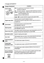
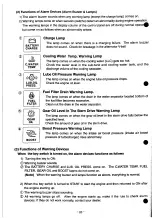
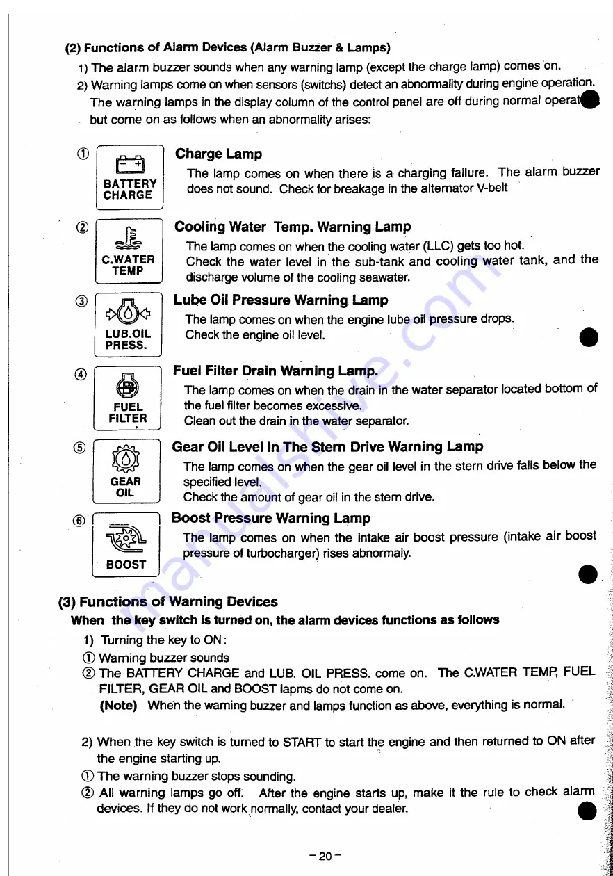
(2) Functions of Alarm Devices (Alarm Buzzer & Lamps)
1) The alarm buzzer sounds when any warning lamp (except the charge lamp) comes on.
2) Warning lamps come on when sensors (switchs) detect an abnormality during engine operation.
The warning lamps in the display column of the control panel are off during normal o p e r a t ^
but come on as follows when an abnormality arises:
CD
BATTERY
CHARGE
LUB.OIL
PRESS.
Charge Lamp
The lamp comes on when there is a charging failure. The alarm buzzer
does not sound. Check for breakage in the alternator V-belt
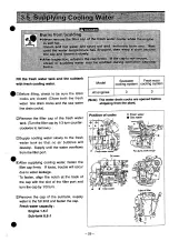
Cooling Water Temp. Warning Lamp
The lamp comes on when the cooling water (LLC) gets too hot.
Check the water level in the sub-tank and cooling water tank, and the
discharge volume of the cooling seawater.
Lube Oil Pressure Warning Lamp
The lamp comes on when the engine lube oil pressure drops.
Check the engine oil level.
Fuel Filter Drain Warning Lamp.
The lamp comes on when the drain in the water separator located bottom of
the fuel filter becomes excessive.
Clean out the drain in the water separator.
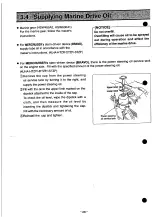
Gear Oil Level In The Stern Drive Warning Lamp
The lamp comes on when the gear oil level in the stern drive falls below the
specified level.
Check the amount of gear oil in the stern drive.
Boost Pressure Warning Lamp
The lamp comes on when the intake air boost pressure (intake air boost
pressure of turbocharger) rises abnormaly.
(3) Functions of Warning Devices
When the key switch is turned on, the alarm devices functions as follows
1) Turning the key to ON:
© Warning buzzer sounds
(D The BATTERY CHARGE and LUB. OIL PRESS, come on. The C.WATER TEMP, FUEL
FILTER, GEAR OIL and BOOST lapms do not come on.
(Note) When the warning buzzer and lamps function as above, everything is normal.
2) When the key switch is turned to START to start the engine and then returned to ON after
the engine starting up.
© The warning buzzer stops sounding.
(D All warning lamps go off. After the engine starts up, make it the rule to check alarm
devices. If they do not work normally, contact your dealer.
- 2 0 -
Summary of Contents for 4LHA-DTP
Page 79: ...Y00R4782 2 Fig fc GEAR HOUSING REFER TO F i g l REFER TO F i g 2 8 2 9 7 EFER TO Fi g 5 ...
Page 81: ...Y00R4782 FLYWHEEL HOUSING 4LHA STZE P 4LHA DTZE P 4LHA HTZE P 13 1 4 ...
Page 87: ...Y00R4782 LUB OIL S U M P 9 7 7 7 7 o 1 01 21 2 N 4LHA HTE P 4LHA HTZE P OPTIONAL 12 ...
Page 89: ...Y0OR4782 OIL SEAL HOUSING REFER TO Fig 1 ...
Page 101: ...Y00R4782 Fig j 2 RåV Tfc JI K S U C T I O N M A N I F O L D ...
Page 107: ...Y00R4782 Fig CAMSHAFT DRIVING GEAR ...
Page 109: ...Y00R4782 Fig 1 C e 4LHA ST Z E P I O TURBOCHARGER 4LHA ST Z E P REFER TO F i g 1 3 ...
Page 111: ...Y00R4782 r 1 ft t y 4LHA DT Z E P F i g l O TURBOCHARGER 4LHA DT Z E P REFER TO F i g 1 3 ...
Page 113: ...Y00R4782 1 7 fcf 4LHA HT Z E P Fig I I T U R B O C H A R G E R 4LHA HT Z E P ...
Page 115: ...Y00R4782 Fig 18 ftiB M I X I N G E L B O W E X H A U S T B E N D 5 ...
Page 117: ...Y00R4782 Fig 18 1 5 E W K M I X I N G E L B O W E X H A U S T B E N D 5 ...
Page 121: ...Y00R4782 Fig I W AIR COOLER 4 L H A H T E P 4 L H A H T Z E P REFER TO F i g 24 ...
Page 127: ...Y00R4782 F i g t C LUB OIL COOLER REFER TO F i g 1 9 FLYWHEEL SIDE ...
Page 131: ...Y00R4782 Fig 24 LUB OIL SYSTEM REFER TO Fi g 2 4LHA STZE P 4LHA DTZE P REFER TO Fi g 6 ...
Page 135: ...Y00R4782 Fig C O LUB OIL PIPE TURBOCHARGER REFER TO F i g 1 5 1 6 1 7 ...
Page 137: ...Y00R4782 Fig 27 MMM V LUB OIL PIPE COOLER REFER TO F i g 22 a 7 f O U T L O STRAINER OUT ...
Page 139: ...Y00R4782 Q Q m y7 m 4LHA ST DT Z E P Fi g O C S W P U M P 4LHA ST DT Z E P ...
Page 141: ...Y00R4782 OQ ymxy 4LHA HT Z E P Fi g fc 57 C S W P U M P 4LHA HT Z E P ...
Page 143: ...Y00R4782 Fig COOLING FRESH W A T E R P U M P REFER TO F i g 62 ...
Page 145: ...Y00R4782 Fig 31 mo z 4LHA ST DT Z E P C F W COOLER 4LHA ST DT Z E P 5 f fc f ui FLYWHEEL SIDE ...
Page 149: ...Y00R4782 Q Q mMW 4LHA STE DTE P Fi g O O C S W PIPE 4LHA STE DTE P REFER TO F i g 3 1 ...
Page 155: ...Y00R4782 g g nm uy m 4LHA HT Z E P C S W PIPE 4LHA HT Z E P REFER TO F i g 32 11 12 SIED PART ...
Page 157: ...Y00R4782 Fig o e nmiuy 4LHA ST DT Z E P O D C F W PI PE 4LHA ST DT Z E P ...
Page 159: ...Y00R4782 Fig Q 7 JMP W7 I 4LHA HT Z E P O f C F W PIPE 4LHA HT Z E P REFER TO F i g 2 3 ...
Page 161: ...Y00R4782 Fi g Q O C S W STRAINER OPTIONAL c s w PUMP KINGSTON C O C K ...
Page 167: ...Y00R4782 4 1 mmxyy 4LHA ST DT Z E P I FUEL INJECTION P U M P 4LHA ST DT Z E P ...
Page 173: ...Y00R4782 ...
Page 175: ...Y00R4782 ...
Page 177: ...Y00R4782 43 M t GOVERNOR ...
Page 179: ...Y00R4782 Å A JWD f Ktfxr Fig F U E L F E E D P U M P REFER TO Fig 41 ...
Page 187: ...Y00R4782 Fig A O rø W7 4LHA ST DT Z E P H O FUEL PIPE 4LHA ST DT Z E P ...
Page 189: ...Y00R4782 Fig A Q miUy 4LHA ST DT Z E P f O FUEL PI PE 4LHA ST DT Z E P ...
Page 193: ...Y00R4782 Fig C n B7 f 4LHA ST DT Z E P U U FUEL STRAINER 4LHA ST DT Z E P ...
Page 195: ...Y00R4782 Fig K 1 TO7 i 4LHA HT Z E P w I FUEL STRAINER 4LHA HT Z E P REFER TO F i g 12 ...
Page 197: ...Y00R4782 Fig 52 OIL WATER SEPARATER OPTIONAL 19 mv t 9 14 F R O M FUEL TANK ...
Page 203: ...Y00R4782 F i g O O P O W E R STEERING P U M P C F W P U M P ...
Page 205: ...Y00R4782 Fig UU P O W E R S T E E R I N G C O O L E R T A N K 1 6 ...
Page 207: ...Y00R4782 57 ATFA f Fig O I ATF PIPE REFER TO F i g 5 6 FER TO F i g 5 5 ...
Page 211: ...Y00R4782 Fifl W O STARTING MOTOR REFER TO F i g 3 ...
Page 213: ...Y00R4782 GENERATOR REFER TO Fig 2 ...
Page 215: ...Y00R4782 Fig D I GENERATOR OPTIONAL REFER TO F i g 30 REFER TO F i g 60 ...
Page 221: ...Y00R4782 Fl g O O SENSOR MOUNT ...
Page 223: ...Y00R4782 H E A T E R P L U G O P T I O N A L 4 L H A H T E P 4 L H A H T Z E P ...
Page 225: ...Y00R4782 Fig OO I N S T R U M E N T P A N E L B T Y P E O P T I O N A L ...
Page 227: ...Y00R4782 Fig NSTRUMENT PANEL C TYPE OPTIONAL ...
Page 229: ...Y00R4782 66 Fig OO I N S T R U M E N T P A N E L C T Y P E O P T I O N A L ...
Page 231: ...Y00R4782 Fig 67 4 0 INSTRUMENT PANEL D TYPE OPTIONAL ...
Page 233: ...Y00R4782 Fig 67 N S T R U M E N T P A N E L D T Y P E O P T I O N A L ...
Page 235: ...Y00R4782 Fig 6 8 T O O L ...
Page 237: ...Y00R4782 Fig D Ø GASKET SET OPTIONAL 1 A ...
Page 302: ...Example of setup with HSW630A1 Hurth marine gear WATER INLET IS M l o 3 0 WATER INLET 2 3 ...
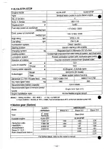
Page 303: ...Chapter 1 General 5 Dimensions i4LHA Series 4LHA STZE STZP 9 96 XVW 9 06 um 1 18 ...
Page 305: ...Chapter 1 General 5 Dimensions 4LHA Series 4LHA DTZE DTZP 9 96 XVW g oe nm 1 20 ...
Page 307: ...Chapter 1 General 5 Dimensions i4LHA Series 4LHA HTZE HTZP g 96 xvw S06NIW 1 22 ...
Page 317: ...Chapter 1 General 7 Electrical Diagrams m4LHA Series 4LHA STZE 1 30 ...
Page 318: ...Chapter 1 General 7 Electrical Diagrams 4LHA Series 4LHA DTZE 1 32 ...
Page 319: ...Chapter 1 General 7 Electrical Diagrams 4LHA Series 4LHA HTE HTZE Eng stop solenoid 1 33 ...
Page 473: ...Chapter 3 Fuel Injection Equipment 9 Tools 4LHA Serie t 3 2 51 ...
Page 507: ...Chapter 5 Lubrication System 1 Lubrication System 4LHA Serie 1 1 Construction ...
Page 519: ...Chapter 6 Cooling Water System 1 Cooling Water System 4LHA Series Cylinder block ...


