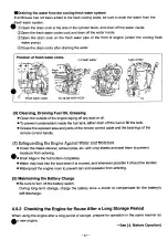
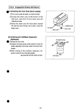
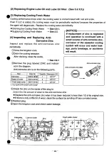
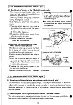

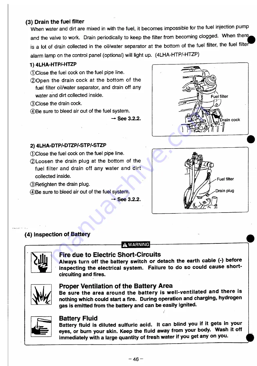
(3) Drain the fuel filter
When water and dirt are mixed in with the fuel, it becomes impossible for the fuel injection pump
and the valve to work. Drain periodically to keep the filter from becoming clogged. When ther<|
is a lot of drain collected in the oil/water separator at the bottom of the fuel filter, the fuei filte
alarm lamp on the control panel (optional) will light up. (4LHA-HTP/-HTZP)
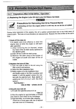
1)4LHA-HTP/-HTZP
©Close the fuel cock on the fuel pipe line.
©Open the drain cock at the bottom of the
fuel filter oil/water separator, and drain off any
water and dirt collected inside.
©Close the drain cock.
©Be sure to bleed air out of the fuel system.
- See 3.2.2.
2) 4LHA-DTP/-DTZP/-STP/-STZP
©Close the fuel cock on the fuel pipe line.
©Loosen the drain plug at the bottom of the
fuel filter and drain off any water and dirt
collected inside.
©Retighten the drain plug.
©Be sure to bleed air out of the fuel system.
* See 3>2>2a
Fuel filter
Drain cock
-Fuel filter
Drain plug
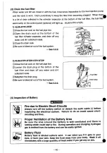
(4) Inspection of Battery
AWARNING
Fire due to Electric Short-Circuits
Always turn off the battery switch or detach the earth cable (-) before
inspecting the electrical system. Failure to do so could cause short-
circuiting and fires.
Proper Ventilation of the Battery Area
Be sure the area around the battery is well-ventilated and there is
nothing which could start a fire. During operation and charging, hydrogen
gas is emitted from the battery and can be easily ignited.
Battery Fluid
Battery fluid is diluted sulfuric acid. It can blind you if it gets in your
eyes, or burn your skin. Keep the fluid away from your body. Wash it off
immediately with a large quantity of fresh water if you get any on you.
- 4 6 -
Summary of Contents for 4LHA-DTP
Page 79: ...Y00R4782 2 Fig fc GEAR HOUSING REFER TO F i g l REFER TO F i g 2 8 2 9 7 EFER TO Fi g 5 ...
Page 81: ...Y00R4782 FLYWHEEL HOUSING 4LHA STZE P 4LHA DTZE P 4LHA HTZE P 13 1 4 ...
Page 87: ...Y00R4782 LUB OIL S U M P 9 7 7 7 7 o 1 01 21 2 N 4LHA HTE P 4LHA HTZE P OPTIONAL 12 ...
Page 89: ...Y0OR4782 OIL SEAL HOUSING REFER TO Fig 1 ...
Page 101: ...Y00R4782 Fig j 2 RåV Tfc JI K S U C T I O N M A N I F O L D ...
Page 107: ...Y00R4782 Fig CAMSHAFT DRIVING GEAR ...
Page 109: ...Y00R4782 Fig 1 C e 4LHA ST Z E P I O TURBOCHARGER 4LHA ST Z E P REFER TO F i g 1 3 ...
Page 111: ...Y00R4782 r 1 ft t y 4LHA DT Z E P F i g l O TURBOCHARGER 4LHA DT Z E P REFER TO F i g 1 3 ...
Page 113: ...Y00R4782 1 7 fcf 4LHA HT Z E P Fig I I T U R B O C H A R G E R 4LHA HT Z E P ...
Page 115: ...Y00R4782 Fig 18 ftiB M I X I N G E L B O W E X H A U S T B E N D 5 ...
Page 117: ...Y00R4782 Fig 18 1 5 E W K M I X I N G E L B O W E X H A U S T B E N D 5 ...
Page 121: ...Y00R4782 Fig I W AIR COOLER 4 L H A H T E P 4 L H A H T Z E P REFER TO F i g 24 ...
Page 127: ...Y00R4782 F i g t C LUB OIL COOLER REFER TO F i g 1 9 FLYWHEEL SIDE ...
Page 131: ...Y00R4782 Fig 24 LUB OIL SYSTEM REFER TO Fi g 2 4LHA STZE P 4LHA DTZE P REFER TO Fi g 6 ...
Page 135: ...Y00R4782 Fig C O LUB OIL PIPE TURBOCHARGER REFER TO F i g 1 5 1 6 1 7 ...
Page 137: ...Y00R4782 Fig 27 MMM V LUB OIL PIPE COOLER REFER TO F i g 22 a 7 f O U T L O STRAINER OUT ...
Page 139: ...Y00R4782 Q Q m y7 m 4LHA ST DT Z E P Fi g O C S W P U M P 4LHA ST DT Z E P ...
Page 141: ...Y00R4782 OQ ymxy 4LHA HT Z E P Fi g fc 57 C S W P U M P 4LHA HT Z E P ...
Page 143: ...Y00R4782 Fig COOLING FRESH W A T E R P U M P REFER TO F i g 62 ...
Page 145: ...Y00R4782 Fig 31 mo z 4LHA ST DT Z E P C F W COOLER 4LHA ST DT Z E P 5 f fc f ui FLYWHEEL SIDE ...
Page 149: ...Y00R4782 Q Q mMW 4LHA STE DTE P Fi g O O C S W PIPE 4LHA STE DTE P REFER TO F i g 3 1 ...
Page 155: ...Y00R4782 g g nm uy m 4LHA HT Z E P C S W PIPE 4LHA HT Z E P REFER TO F i g 32 11 12 SIED PART ...
Page 157: ...Y00R4782 Fig o e nmiuy 4LHA ST DT Z E P O D C F W PI PE 4LHA ST DT Z E P ...
Page 159: ...Y00R4782 Fig Q 7 JMP W7 I 4LHA HT Z E P O f C F W PIPE 4LHA HT Z E P REFER TO F i g 2 3 ...
Page 161: ...Y00R4782 Fi g Q O C S W STRAINER OPTIONAL c s w PUMP KINGSTON C O C K ...
Page 167: ...Y00R4782 4 1 mmxyy 4LHA ST DT Z E P I FUEL INJECTION P U M P 4LHA ST DT Z E P ...
Page 173: ...Y00R4782 ...
Page 175: ...Y00R4782 ...
Page 177: ...Y00R4782 43 M t GOVERNOR ...
Page 179: ...Y00R4782 Å A JWD f Ktfxr Fig F U E L F E E D P U M P REFER TO Fig 41 ...
Page 187: ...Y00R4782 Fig A O rø W7 4LHA ST DT Z E P H O FUEL PIPE 4LHA ST DT Z E P ...
Page 189: ...Y00R4782 Fig A Q miUy 4LHA ST DT Z E P f O FUEL PI PE 4LHA ST DT Z E P ...
Page 193: ...Y00R4782 Fig C n B7 f 4LHA ST DT Z E P U U FUEL STRAINER 4LHA ST DT Z E P ...
Page 195: ...Y00R4782 Fig K 1 TO7 i 4LHA HT Z E P w I FUEL STRAINER 4LHA HT Z E P REFER TO F i g 12 ...
Page 197: ...Y00R4782 Fig 52 OIL WATER SEPARATER OPTIONAL 19 mv t 9 14 F R O M FUEL TANK ...
Page 203: ...Y00R4782 F i g O O P O W E R STEERING P U M P C F W P U M P ...
Page 205: ...Y00R4782 Fig UU P O W E R S T E E R I N G C O O L E R T A N K 1 6 ...
Page 207: ...Y00R4782 57 ATFA f Fig O I ATF PIPE REFER TO F i g 5 6 FER TO F i g 5 5 ...
Page 211: ...Y00R4782 Fifl W O STARTING MOTOR REFER TO F i g 3 ...
Page 213: ...Y00R4782 GENERATOR REFER TO Fig 2 ...
Page 215: ...Y00R4782 Fig D I GENERATOR OPTIONAL REFER TO F i g 30 REFER TO F i g 60 ...
Page 221: ...Y00R4782 Fl g O O SENSOR MOUNT ...
Page 223: ...Y00R4782 H E A T E R P L U G O P T I O N A L 4 L H A H T E P 4 L H A H T Z E P ...
Page 225: ...Y00R4782 Fig OO I N S T R U M E N T P A N E L B T Y P E O P T I O N A L ...
Page 227: ...Y00R4782 Fig NSTRUMENT PANEL C TYPE OPTIONAL ...
Page 229: ...Y00R4782 66 Fig OO I N S T R U M E N T P A N E L C T Y P E O P T I O N A L ...
Page 231: ...Y00R4782 Fig 67 4 0 INSTRUMENT PANEL D TYPE OPTIONAL ...
Page 233: ...Y00R4782 Fig 67 N S T R U M E N T P A N E L D T Y P E O P T I O N A L ...
Page 235: ...Y00R4782 Fig 6 8 T O O L ...
Page 237: ...Y00R4782 Fig D Ø GASKET SET OPTIONAL 1 A ...
Page 302: ...Example of setup with HSW630A1 Hurth marine gear WATER INLET IS M l o 3 0 WATER INLET 2 3 ...
Page 303: ...Chapter 1 General 5 Dimensions i4LHA Series 4LHA STZE STZP 9 96 XVW 9 06 um 1 18 ...
Page 305: ...Chapter 1 General 5 Dimensions 4LHA Series 4LHA DTZE DTZP 9 96 XVW g oe nm 1 20 ...
Page 307: ...Chapter 1 General 5 Dimensions i4LHA Series 4LHA HTZE HTZP g 96 xvw S06NIW 1 22 ...
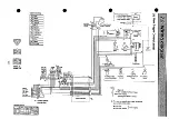
Page 317: ...Chapter 1 General 7 Electrical Diagrams m4LHA Series 4LHA STZE 1 30 ...
Page 318: ...Chapter 1 General 7 Electrical Diagrams 4LHA Series 4LHA DTZE 1 32 ...
Page 319: ...Chapter 1 General 7 Electrical Diagrams 4LHA Series 4LHA HTE HTZE Eng stop solenoid 1 33 ...
Page 473: ...Chapter 3 Fuel Injection Equipment 9 Tools 4LHA Serie t 3 2 51 ...
Page 507: ...Chapter 5 Lubrication System 1 Lubrication System 4LHA Serie 1 1 Construction ...
Page 519: ...Chapter 6 Cooling Water System 1 Cooling Water System 4LHA Series Cylinder block ...


