background image

M2215-04E150

6LY3-ETP/-STP/-UTP

6LY3-ETP/-STP/-UTP

Summary of Contents for 6LY3-ETP

Page 1: ...M2215 04E150 6LY3 ETP STP UTP 6LY3 ETP STP UTP ...

Page 2: ... 04E150 History of Revision Manual Name Service Manual for Marine Diesel Engine Engine Model 6LY3 ETP STP UTP Number of revision Date of revision Reason for correction Outline of correction Correction item No page Corrected by New edition November 2005 ...

Page 3: ...tantial effect on the performance of the engine and the vessel Moreover when the engine runs unevenly or when trouble occurs it is essential to check a wide range of operating conditions such as installation to the full and suitability of the ship s piping and propeller and not just the engine itself To get maximum performance from this engine you should completely understand its functions constru...

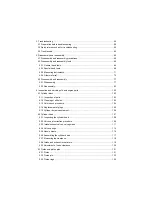
Page 4: ...16 2 2 1 Check before starting 16 2 2 2 Inspection after initial 50 hours or one month operation 20 2 2 3 Inspection every 50 hours or monthly 22 2 2 4 Inspection on initial 250 hours or one year 27 2 2 5 Inspection every 250 hours or one year 33 2 2 6 Inspection every year 39 2 2 7 Inspection every 500 hours or two years 41 2 2 8 Inspection 2 000 hours or every two years 42 2 2 9 Inspection every...

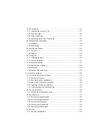
Page 5: ...vicing of basic engine parts 103 5 1 Cylinder block 103 5 1 1 Inspection of parts 103 5 1 2 Cleaning of oil holes 103 5 1 3 Color check procedure 104 5 1 4 Replacement of plugs 105 5 1 5 Cylinder bore measurement 106 5 2 Cylinder head 107 5 2 1 Inspecting the cylinder head 108 5 2 2 Valve seat correction procedure 109 5 2 3 Intake exhaust valves valve guides 111 5 2 4 Valve springs 114 5 2 5 Nozzl...

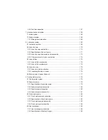
Page 6: ...43 5 8 3 Position of top dead center 143 6 Fuel injection equipment 144 6 1 Fuel Injection pump governor timer 144 6 1 1 Fuel system diagram 144 6 1 2 Fuel injection pump specifications 145 6 1 3 Removing a fuel injection pump assy 146 6 1 4 Installing a fuel injection pump assy 149 6 1 5 Troubleshooting of fuel injection pump 157 6 2 Fuel Injection nozzle 159 6 2 1 Functioning of fuel injection n...

Page 7: ...lter replacement 175 8 4 Lube oil cooler 176 8 4 1 Lube oil cooler construction 176 8 4 2 Inspecting the lube oil cooler 176 8 5 Rotary waste oil pump Optional 177 9 Cooling water system 178 9 1 Cooling water system 178 9 2 Seawater pump 179 9 2 1 Specifications of seawater pump 179 9 2 2 Seawater pump disassembly 180 9 2 3 Seawater pump Inspection 180 9 2 4 Seawater pump reassembly 181 9 3 Fresh ...

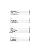
Page 8: ...ction 191 9 6 3 Characteristics of thermostat 192 9 6 4 Thermostat inspection 192 9 6 5 Testing the thermostat 192 9 7 Seacock Optional 193 9 8 Bilge pump and bilge strainer Optional 194 9 8 1 Introduction 194 9 8 2 Description 195 9 8 3 Cautions 196 9 8 4 Assembly procedure 198 9 8 5 Cautions for Assembling 200 9 8 6 Troubleshooting 202 10 Turbocharger 203 10 1 Construction and function 204 10 1 ...

Page 9: ...t gas 224 10 8 3 Too early oil shortage 225 10 8 4 Output drop 225 10 8 5 Poor follow up of supercharger 225 10 8 6 Unusual sound or vibration 225 11 Reduction and reversing gear 226 12 Remote control 227 12 1 Electronic control system ECS 227 12 1 1 Digital display 228 12 1 2 Rocker switch panel 230 12 1 3 Control head Shift Throttle 231 13 Electrical system 232 13 1 Electrical system 232 13 1 1 ...

Page 10: ...ction 247 13 5 Warning devices 248 13 5 1 Sensor installation position 248 13 5 2 Lube oil pressure sensor and boost sensor 250 13 5 3 Temperature sensor for water lube oil and fuel 251 14 Service standards 252 14 1 Engine tuning 252 14 2 Engine body 253 14 2 1 Cylinder head 253 14 2 2 Camshaft and gear train 254 14 2 3 Cylinder block 255 15 Tightening torque for bolts and nuts 258 15 1 Main bolt ...

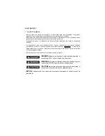
Page 11: ...nce in the manual Sufficient consideration for safety is required in addition to the matters marked Especially for safety precautions in a repair or maintenance job not described in this manual receive instructions from a knowledgeable leader Safety marks used in this manual and their meanings are as follows DANGER indicates an imminent hazardous situation which if not avoided WILL result in death...

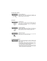
Page 12: ...ll type accidents Clean orderly arranged place No dust mud oil or parts should be left on the floor surface Failure to Observe An unexpected accident may be caused Bright Safely Illuminated Area The work area should be well lit or illuminated in a safe manner For work in enclosed or dark areas a drop cord should be utilized The drop cord must have a wire cage to prevent bulb breakage and possible ...

Page 13: ...ap as an attaching device Do not use rope serious injury may result To hold or support an engine secure the engine to a support stand test bed or test cart designed to carry the weight of the engine Do not overload this device serious injury may result Never run an engine without being properly secured to an engine support stand test bed or test cart serious injury may result Appropriate Tools Alw...

Page 14: ...of ignition away Explosion may occur causing severe personal injury Battery Electrolyte Batteries contain sulfuric acid Do NOT allow it to come in contact with clothing skin and or eyes severe burns will result 7 WASTE MANAGEMENT Observe the following instructions with regard to hazardous waste disposal Negligence of these will have a serious impact on environmental pollution concerns 1 Waste flui...

Page 15: ...amage to the engine and or severe personal injury Preventing burns from scalding 1 Never open the filler cap shortly after shutting the engine down Steam and hot water will spurt out and seriously burn you Allow the engine to cool down before attempt to open the filler cap 2 Securely tighten the filler cap after checking the cooling water Steam can spurt out during engine running if tightening loo...

Page 16: ...n attached Their location is shown below and they should always be visible Please replace if damaged or lost Warning Labels No Part Code No A 128296 07300 B 120324 07240 C 128296 07260 D 128296 07350 E 119578 07890 E 003025 02E DO NOT STEP ON COVERS POSSIBILITY OF A FALL ...

Page 17: ...ed check the part installed state deformation damage roughening surface defect etc Arrange the removed parts orderly with clear distinction between those to be replaced and those to be used again Parts to be used again shall be washed and cleaned sufficiently Select especially clean locations and use clean tools for disassembly of hydraulic units such as the fuel injection pump 5 Precautions for I...

Page 18: ... manifold Dip stick Fresh water cooler Seawater pump Alternator V belt Fresh water pump Non operation side 005033 01E Turbocharger Lube oil filter Air silencer Filler cap Intercooler Fuel injection pump Flywheel Lube oil cooler Operation side Electrical control unit cover 003045 01E ...

Page 19: ...8 254 345 3198 Fuel stop power Note 1 Output at crankshaft Engine speed kW HP min 1 353 480 3300 at Fuel inlet temp 40 C 324 440 3300 at Fuel inlet temp 40 C 279 380 3300 at Fuel inlet temp 40 C High idling min 1 3500r25 Low idling min 1 700r25 Installation Flexible mounting Direction of rotation Crankshaft Counterclockwise viewed from stern Cooling system Fresh water cooling with heat exchanger L...

Page 20: ...f the fuel It should not exceed 0 5 by volume Preferably it should be below 0 05 Water and sediment in the fuel oil should not exceed 0 05 by volume Ash should not exceed 0 01 by mass 10 Carbon residue content of the fuel It should not exceed 0 35 by volume Preferably it should be below 0 1 Aromatics total content of the fuel It should not exceed 35 by volume Preferably it should be below 30 and a...

Reviews: