background image

ENGINE OPERATION

30

8LV Series Operation Manual

THROTTLE AND SHIFT 
CONTROL

WARNING

SUDDEN MOVEMENT HAZARD

The boat will start to move when the marine 
gear is engaged: 

• Ensure the boat is clear of all obstacles 

forward and aft.

• Quickly shift to the FORWARD position then 

back to the NEUTRAL position.

• Observe whether the boat moves in the 

direction you expect.

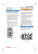
Neutral

1. Move the control head handle to the N (Neutral) 

position. (The NEUTRAL lamp will come on)

2. When switching between forward and reverse, 

move the handle slowly between the forward 
and reverse positions. Move the handle firmly 
into either the forward or reverse position.

Forward

Move the handle toward F (forward) to the 
forward-side notch position. The engine will remain 
idling. Moving the handle forward further will 
increase the engine speed.

Reverse

Move the handle toward R (reverse) to the 
reverse-side notch position. The engine will remain 
idling. Pulling the handle back further will increase 
the engine speed.

Forward (Reverse) to Reverse 
(Forward)

Moving the handle quickly and switching from 
forward (reverse) to reverse (forward) will activate 
the gear shift delay (astern delay). The engine 
speed to decrease to idle speed for several 
seconds.

Note: The force required to move the throttle or 

shift handles can be adjusted with the 
Adjusting Screw.

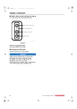
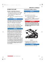
Figure 6

Panel

Forward Idle

Adjusting screw

Neutral

Reverse Idle

Full speed
reverse

Full speed
forward

037634-00E00

8LV_OPM.book  30 ページ  2011年1月11日 火曜日 午後12時8分

Summary of Contents for 8LV320

Page 1: ...8LV320 8LV350 8LV370 8LV320Z 8LV350Z 8LV370Z 0A8LV G00100 PRINTED IN JAPAN ...

Page 2: ...ight to make any change at any time without notice Yanmar and are registered trademarks of YANMAR CO LTD in Japan the United States and or other countries All Rights Reserved No part of this publication may be reproduced or used in any form by any means graphic electronic or mechanical including photocopying recording taping or informa tion storage and retrieval systems without the written permiss...

Page 3: ...eatures and Applications 11 New Engine Break In 12 Component Identification 13 Service Side 13 Non Service Side 13 Location of Nameplate 14 Function of Major Components 15 Vessel Control System VCS 16 Display 17 Before You Operate 19 Diesel Fuel 20 Diesel Fuel Specifications 20 Filling the Fuel Tank 22 Bleeding the Fuel System 22 Engine Oil 23 Engine Oil Specifications 23 Engine Oil Viscosity 23 C...

Page 4: ...rming Periodic Maintenance 36 The Importance of Daily Checks 36 Keep a Log of Engine Hours and Daily Checks 36 Yanmar Replacement Parts 36 Tools Required 36 Ask Your Authorized Yanmar Marine Dealer or Distributor for Help 36 Tightening Fasteners 37 EPA Maintenance Requirements 39 EPA Requirements for USA and Other Applicable Countries 39 EPA Requirements 39 Conditions to Ensure Compliance with EPA...

Page 5: ...pecifications 67 8LV Series Engine Specifications 67 8LV Series Marine Gear Specifications 68 System Diagrams 69 Wiring Diagram 69 8LV Wiring Diagram 70 EPA Warranty USA Only 73 YANMAR CO LTD Limited Emission Control System Warranty USA Only 73 Your Warranty Rights and Obligations 74 Warranty Period 74 Warranty Coverage 74 Exclusions 74 Owner s Responsibility 74 Customer Assistance 75 Maintenance ...

Page 6: ...TABLE OF CONTENTS iv 8LV Series Operation Manual This Page Intentionally Left Blank 8LV_OPM book iv ページ 2011年1月11日 火曜日 午後12時8分 ...

Page 7: ...and maintenance procedures Keep this Operation Manual in a convenient place for easy access If this Operation Manual is lost or damaged order a new one from your authorized Yanmar Marine dealer or distributor Make sure this manual is transferred to subsequent owners This manual should be considered a permanent part of the engine and remain with it Constant efforts are made to improve the quality a...

Page 8: ...______________________________________ Engine Serial No ____________________________________________________________________ Date Purchased _____________________________________________________________________ Dealer _____________________________________________________________________________ Dealer Phone _______________________________________________________________________ 8LV_OPM book 2 ページ 2...

Page 9: ...w part and label at the same time DANGER DANGER indicates a hazardous situation which if not avoided will result in death or serious injury WARNING WARNING indicates a hazardous situation which if not avoided could result in death or serious injury CAUTION CAUTION indicates a hazardous situation which if not avoided could result in minor or moderate injury NOTICE NOTICE indicates a situation which...

Page 10: ...are additional reminders for safe operating and maintenance techniques Contact your authorized Yanmar Marine dealer or distributor for additional training During Operation and Maintenance DANGER CRUSH HAZARD Never stand under hoisted engine If the hoist mechanism fails the engine will fall on you If the engine needs to be transported for repair have a helper assist you attach it to a hoist and loa...

Page 11: ...lothing and Always tie long hair back when working near moving rotating parts such as the flywheel or PTO shaft Keep hands feet and tools away from all moving parts Never operate the engine without the guards in place Before you start the engine make sure that all bystanders are clear of the area Keep children and pets away while the engine is operating Check the engine that any tools or shop rags...

Page 12: ...enclosed area All internal combustion engines create carbon monoxide gas during operation and special precautions are required to avoid carbon monoxide poisoning Always ensure that all connections are tightened to specifications after repair is made to the exhaust system All internal combustion engines create carbon monoxide gas during operation and special precautions are required to avoid carbon...

Page 13: ...ing system when the ambient temperature is below 0 C 32 F NOTICE It is important to perform daily checks as listed in the Operation Manual Periodic maintenance prevents unexpected downtime reduces the number of accidents due to poor engine performance and helps extend the life of the engine NOTICE Contact your authorized Yanmar Marine dealer or distributor if you need to operate the engine at high...

Page 14: ...nder a substantial load at all times For best break in results operate the engine at various speeds Operating the engine in NEUTRAL must be avoided During the first 50 hours avoid operation below 2000 min 1 rpm During the break in period carefully observe the engine oil pressure and engine temperature During the break in period check the engine oil and coolant levels frequently NOTICE If any indic...

Page 15: ...ies marine engines Figure 1 DO NOT STEP ON COVERS POSSIBILITY OF A FALL 119578 07890 CAUTION Overcranking engine with water lift muffler can cause damage 128171 07150 4 5 6 3 2 1 037426 00X00 No Part Number 1 128296 07260 2 128171 07150 3 128296 07300 4 128296 07350 5 196630 12980 6 119578 07890 8LV_OPM book 9 ページ 2011年1月11日 火曜日 午後12時8分 ...

Page 16: ...SAFETY 10 8LV Series Operation Manual Figure 2 037427 00X00 1 2 No Part Number 1 120324 07240 2 128296 07300 8LV_OPM book 10 ページ 2011年1月11日 火曜日 午後12時8分 ...

Page 17: ... the engine should be easy to use and accessible for service To handle the drive equipment propulsion systems including the propeller and other onboard equipment always observe the instructions and cautions given in the operation manuals supplied by the shipyard and equipment manufacturers The 8LV series engines are designed to be operated at maximum throttle 3600 to 3800 min 1 rpm for less than 5...

Page 18: ... operating at low speeds for long periods this will interfere with proper movement of the rings and the lube oil consumption may increase Low idle speed does not allow break in of sliding parts If operating engine at low speed and light load you must rev up the engine i e increase the engine speed for a short time to clean the carbon from the cylinders and fuel injection valve Perform this procedu...

Page 19: ... equipment from that illustrated Figure 1 Non Service Side Figure 2 037423 00E00 Dipstick Lubricating oil feeding port Fuel filter Fuel oil cooler Fuel priming pump Lubricating oil filter Alternator Turbo charger Mixing elbow Turbo charger Silencer Silencer 037424 00E00 ECU box Heat exchanger Engine lubricating oil cooler Seawater pump Air cooler 8LV_OPM book 13 ページ 2011年1月11日 火曜日 午後12時8分 ...
Page 20: ...place if damaged or lost The engine nameplate is attached to the top surface of the engine air cooler Figure 4 Figure 3 Figure 4 Gear Model ENG No MFG DATE Model min 1 min 1 min 1 Continuous power kW Speed of prop shaft Fuel stop power kW 129670 07200 037425 00X00 Gear Model ENG No MFG DATE Model min 1 min 1 min 1 Continuous power kW Speed of prop shaft Fuel stop power kW 8LV_OPM book 14 ページ 2011年...

Page 21: ...seawater as this will damage the impeller Coolant Filler Cap When the coolant temperature rises the pressure inside the coolant tank increases and opens the pressure valve in the filler cap When the pressure valve in the filler cap is opened hot water and steam pass through a rubber hose to the coolant reservoir tank When the engine cools and the pressure inside the coolant tank drops the vacuum v...

Page 22: ...pecific accordance with the instructions in this manual or the system is modified in any way Yanmar will not be responsible for any warranty failures in the operation of the system or the vessel utilizing the system Yanmar has designed the Vessel Control System VCS in conjunction with the 8LV engine The system has many functions that must be configured and calibrations must be made before the vess...

Page 23: ...nction normally contact your authorized Yanmar Marine dealer or distributor and ask for diagnostics Diag Codes Screen Figure 8 Alarm Indicator Functions The alarm indicators and buzzer are activated when sensors detect an abnormality during engine operation The alarm indicators are off during normal operation but are activated as follows when an abnormality arises The coolant temperature alarm ind...

Page 24: ... Use this switch only in an emergency NOTICE Under normal circumstances do not use the Emergency stop switch to stop the engine The engine shuts down suddenly when the Emergency stop switch is pressed After the engine has stopped press the Emergency stop switch to release the emergency stop Eng START STOP switch Check Eng indicator Emergency stop switch Power switch 037627 00E04 8LV_OPM book 18 ペー...

Page 25: ...f the Operation Manual describes the diesel fuel engine oil and engine coolant specifications and how to replenish them It also describes the daily engine checks Before performing any operations within this section review the Safety section on page 3 8LV_OPM book 19 ページ 2011年1月11日 火曜日 午後12時8分 ...

Page 26: ...and authorized diesel fuel suppliers Precautions and concerns regarding the use of bio fuels Biodiesel fuels have a higher content of methyl esters which may deteriorate certain metal rubber and plastic components of the fuel system The customer and or boat builder are responsible to verify the usage of biodiesel compatible components on the vessel fuel supply and return systems Free water in biod...

Page 27: ... 10 by volume Do not use Biocide Do not use kerosene or residual fuels Handling of Diesel Fuel 1 Water and dust in the fuel may cause engine failure When fuel is stored be sure that the inside of the storage container is clean and dry and that the fuel is stored away from dirt or rain Figure 1 2 Keep the fuel container stationary for several hours to allow any dirt or water to settle to the bottom...

Page 28: ...while filling This prevents static electricity buildup which could cause sparks and ignite fuel vapors 4 Stop fueling when the gauge shows the fuel tank is full CAUTION Never overfill the fuel tank 5 Replace the fuel cap and hand tighten Over tightening the fuel cap will damage it Bleeding the Fuel System Bleeding must be done if any fuel system maintenance has been performed replacement of fuel f...

Page 29: ... 1 When handling and storing engine oil be careful not to allow dust and water to contaminate the oil Clean around the filler port before filling 2 Do not mix lubrication oils of different types or brands Mixing may cause the chemical characteristics of the oil to change and lubricating performance to decrease reducing the engine s life 3 Engine oil should be replaced at the specified intervals re...

Page 30: ...1 Remove the yellow oil filler port cap from filler port 1 Figure 5 and fill with engine oil NOTICE Prevent dirt and debris from contaminating the engine oil Carefully clean the dipstick and the surrounding area before you remove the cap 2 Fill with oil to the upper limit on the dipstick 2 Figure 5 NOTICE Never overfill the engine with engine oil 3 Insert the dipstick fully to check the level NOTI...

Page 31: ...bient temperature as specified by the LLC manufacturer LLC concentration should be a minimum of 30 to a maximum of 60 Too much LLC will decrease the cooling efficiency Excessive use of antifreeze also lowers the cooling efficiency of the engine Never mix different types or brands of LLC as a harmful sludge may form Mixing different brands of antifreeze may cause chemical reactions and may make the...

Page 32: ...oolant tank heat exchanger Replace if damaged Note The level of the coolant tank often decrease The level of the reservoir tank does not change In these cases there may be water or air leaks in the cooling system Contact your authorized Yanmar Marine dealer or distributor CHECKING THE ENGINE OIL AND ENGINE COOLANT When engine oil or coolant is supplied for the first time or when they must be repla...

Page 33: ...the Operation Manual describes the diesel fuel engine oil and engine coolant specifications and how to replenish them It also describes the daily engine checkout Before performing any operations within this section review the Safety section on page 3 8LV_OPM book 27 ページ 2011年1月11日 火曜日 午後12時8分 ...

Page 34: ...drives check that it is not aligned with the trailer position 9 Press the Engine START STOP switch 2 Figure 1 and power on the starter When the engine starts the VCS display will show the screen with engine conditions Figure 4 Note 1 Concerning the control head SEL lamp For Multi Station the SEL lamp will flash and for Single Station the SEL lamp will come on 2 Pressing the Engine START STOP switc...

Page 35: ...re normal 2 Check for water or oil leakage from the engine 3 Check that exhaust color engine vibrations and sound are normal 4 When there are no problems keep the engine at low speed to send engine oil to all parts of the engine 5 Check that sufficient seawater is discharged from the seawater outlet pipe Operation with inadequate seawater discharge will damage the impeller of the seawater pump If ...

Page 36: ... Forward Move the handle toward F forward to the forward side notch position The engine will remain idling Moving the handle forward further will increase the engine speed Reverse Move the handle toward R reverse to the reverse side notch position The engine will remain idling Pulling the handle back further will increase the engine speed Forward Reverse to Reverse Forward Moving the handle quickl...

Page 37: ...in this speed range If you hear any abnormal sounds stop the engine and inspect 4 Alarm buzzer sounds during operation NOTICE If any alarm indicator with audible alarm sound appears on the display during engine operation stop the engine immediately Determine the cause and repair the problem before you continue to operate the engine 5 Is there water oil or fuel leakage or are there any loose bolts ...

Page 38: ...down 3 Press the Engine START STOP switch on the switch panel of the selected station 4 Press the Power switch and turn the power OFF CAUTION Do not press the Engine START STOP switch when the engine is stopped The engine will restart Do not turn the Battery switch OFF before turning the Power switch OFF 5 Turn the battery switch off for engine and VCS 6 Close the fuel tank cock 7 Close the seacoc...

Page 39: ...eck that the Power switch on the switch panel is OFF and that the control head handle and backup panel s shift switch are in the N Neutral position 2 Push the Power switch to the ON position on the backup panel The lamp will come on and enabling control by the backup panel 3 The engine can be started or stopped with the START STOP switch 4 Pull out the protect bar 5 Shift gears using the Shift swi...

Page 40: ...e seacock s If there is a risk of freezing check that the cooling system contains enough coolant See Engine Coolant Specifications on page 25 If there is a risk of freezing drain the seawater system See Draining the Seawater Cooling System on page 54 At temperatures below 0 C 32 F drain seawater system and connect the engine heater if equipped 8LV_OPM book 34 ページ 2011年1月11日 火曜日 午後12時8分 ...

Page 41: ...ection of the Operation Manual describes the procedures for proper care and maintenance of the engine Before performing any maintenance procedures within this section read the following safety information and review the Safety section on page 3 8LV_OPM book 35 ページ 2011年1月11日 火曜日 午後12時8分 ...
Page 42: ...ake it a habit of performing daily checks before the start of each operating day See Daily Checks on page 42 Keep a Log of Engine Hours and Daily Checks Keep a log of the number of hours the engine is run each day and a log of the daily checks performed Also note the date type of repair e g replaced alternator and parts used for any service needed between the periodic maintenance intervals Periodi...

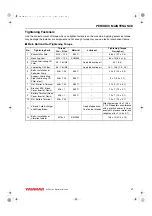
Page 43: ...l Filter 3 4 16 UNF Apply lubricating oil 14 7 19 6 1 5 2 0 5 Bolts Installation of Seawater Pump M8 1 25 S45C 20 3 2 0 0 3 6 Support Lubricating Pipe Lubricating Oil Filter in out M8 1 25 S45C 5 1 0 5 0 1 7 Nut Starter B Terminal M8 1 25 S45C 21 2 2 1 0 2 8 Bracket EDU Head Cover Insert of Resin M6 1 S45C 10 1 1 0 0 1 9 Battery Terminal Head Cover Insert of Resin M6 1 S45C 10 1 1 0 0 1 10 Nut Bat...

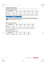
Page 44: ...Piping Taper Screw Thread Diameter M6 M8 M10 M12 M10 M12 Pitch mm 1 0 1 25 1 5 1 75 1 25 1 25 Width across flat mm 10 12 14 17 14 17 Tightening torque N m kgf m 10 8 1 1 1 0 1 25 5 3 2 6 0 3 49 5 5 0 0 5 88 2 10 9 0 1 0 52 5 5 3 0 5 93 10 9 5 1 0 Thread Diameter M8 M10 M12 M14 M16 Pitch mm 1 25 1 25 1 25 1 5 1 5 Width across flat mm 14 14 17 19 22 Tightening torque N m kgf m 14 7 2 1 5 0 2 22 5 3 ...

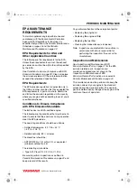
Page 45: ...t in order to ensure that the emissions during operation meet the EPA standards The operating conditions should be as follows Ambient temperature 20 C to 40 C 4 F to 104 F Relative humidity 80 or lower The diesel fuel should be ASTM D975 No 1 D or No 2 D or equivalent minimum cetane No 45 The lubricating oil should be Type API Class CD CF CF 4 CI CI 4 Be sure to perform inspections as outlined in ...

Page 46: ...stance when checking items marked with a c Check or Clean Replace Contact your authorized Yanmar Marine dealer or distributor System Item Periodic Maintenance Interval Daily See Daily Checks on page 42 Every 50 Hours or Monthly Whichever Comes First Every 250 Hours or One Year Whichever Comes First Every 500 Hours or Two Years Whichever Comes First Every 1000 Hours or Four Years Whichever Comes Fi...

Page 47: ...k alarm and indicators c Check electrolyte level in the battery c Damage of belt c Check wiring connectors c Engine CylinderHead and Block Check for leakage of fuel engine oil and engine coolant c After starting Tighten all major nuts and bolts Miscellane ous Items Adjust the propeller shaft alignment Initial 50 Replace rubber hoses fuel and water c Check or Clean Replace Contact your authorized Y...

Page 48: ...se or corroded clamps 8 Check the fuel filter water separator for presence of water and contaminants If you find any water or contaminants drain the fuel filter water separator See Draining the Fuel Water Separator on page 44 If you have to drain the fuel filter water separator frequently drain the fuel tank and check for the presence of water in your fuel supply See Draining the Fuel Tank on page...

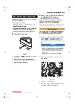
Page 49: ...cheduled It is easiest and most effective to drain the engine oil after operation while the engine is still warm WARNING If you must drain the engine oil while it is still hot stay clear of the hot engine oil to avoid being burned Always wear eye protection 1 Remove the yellow oil filler port cap from filler port 1 Figure 5 on page 24 Remove the drain plugs both in the right and left in the lower ...

Page 50: ...ere is unusual noise and or vibration this maintenance requires specialized knowledge and techniques Contact your authorized Yanmar Marine dealer or distributor to adjust the propeller shaft alignment Perform the following maintenance every 50 hours or monthly of operation whichever comes first Draining the Fuel Water Separator Checking the Battery Electrolyte Level Serviceable Batteries Only Drai...

Page 51: ... battery electrolyte Operating with insufficient electrolyte will destroy the battery Battery fluid tends to evaporate in high temperatures especially in summer In such conditions inspect the battery earlier than specified 1 Turn the battery master switch to OFF or disconnect the negative battery cable 2 Do not operate with insufficient battery electrolyte as the battery will be destroyed 3 Remove...

Page 52: ...Major Nuts and Bolts Draining the Fuel Tank See Draining the Fuel Tank on page 43 Replacing the Fuel Filter Element WARNING When removing any fuel system component to perform maintenance such as replacing the fuel filter put an approved container under the opening to catch the fuel Never use a shop rag to catch the fuel Vapors from the rag are flammable and explosive Wipe up any spills immediately...

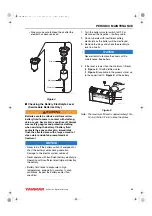
Page 53: ...gine Oil Filter Element See Changing the Engine Oil and Replacing the Engine Oil Filter Element on page 43 Checking and Replacing the Seawater Pump Impeller 1 Loosen the side cover bolts and remove the side cover 2 Inspect the inside of the seawater pump with a flashlight If any of the following are found disassembly and maintenance are required Impeller blades are cracked or nicked Edges or surfa...

Page 54: ...blades and cause damage Puller A Standard Figure 9 1 Remove the side cover of the seawater pump 2 Install the puller A Figure 9 in the impeller Figure 10 3 Turn the jack screw B Figure 9 clockwise to remove the impeller from the pump body Figure 11 Note When replacing a used impeller with a new one the impeller must have an M22 1 5 thread 1 Figure 10 Turn the M18 screw side of the impeller to the ...

Page 55: ...3 Plug Figure 13 1 Heat Exchanger Zinc Anode Figure 14 Changing the Coolant CAUTION Wear eye protection and rubber gloves when you handle engine coolant If contact with the eyes or skin should occur flush eyes and wash immediately with clean water Replace coolant every year NOTICE Never mix different types and or colors of coolants Discard old coolant in an approved manner according to environment...

Page 56: ...an any dirt and scale out of the exhaust and seawater passages 3 If the mixing elbow is damaged repair or replace 4 Inspect the gasket and replace if necessary Cleaning the Turbo charger Contamination of the turbo charger causes revolutions to drop and engine output to fall If a significant drop in engine output is noted 10 or more clean the turbo charger This should be done only by a trained and ...

Page 57: ... or distributor to check the wiring connectors Tightening All Major Nuts and Bolts See Tightening Fasteners on page 37 or contact your authorized Yanmar Marine dealer or distributor Perform the following maintenance every 500 hours or 2 years of operation whichever comes first Replacing the Rubber Hoses Replacing the Exhaust Water Mixing Elbow Replacing the Rubber Hoses Replace the rubber hoses ev...

Page 58: ... 47 Cleaning and Checking the Seawater Passages After prolonged use clean the seawater passages to remove trash scale rust and other contaminants that collect in the cooling water passages This can cause declining cooling performance The following items need to be inspected Heat Exchanger Pressure Cap Contact your authorized Yanmar Marine dealer or distributor Adjusting the Propeller Shaft Alignme...

Page 59: ...orrosion and the exterior from rusting The engine can normally stand idle for up to 6 months If it remains unused for longer than this please contact your authorized Yanmar Marine dealer or distributor Before performing any storage procedures within this section review the Safety section on page 3 In cold temperatures or before long term storage be sure to drain the seawater from the cooling syste...

Page 60: ...uel tank completely or fill the tank to prevent condensation 4 Seal the intake silencer exhaust pipe etc to prevent moisture or contamination from entering engine 5 Completely drain the bilge in hull bottom 6 Waterproof the engine room to prevent rain or seawater from entering 7 Charge the battery once a month to compensate for battery s self discharge 8 Remove the key from the key switch and cove...

Page 61: ...er cylinder block cylinder head etc when ambient temperature is below 0 C 32 F When draining the freshwater Open the freshwater drain cocks 2 positions and drain the freshwater from inside the engine Close the drain cocks after draining the freshwater Carry out the following periodic inspection before placing the engine in storage 1 Clean the outside of the engine wiping off any dust or oil 2 To p...

Page 62: ...LONG TERM STORAGE 56 8LV Series Operation Manual This Page Intentionally Left Blank 8LV_OPM book 56 ページ 2011年1月11日 火曜日 午後12時8分 ...

Page 63: ...Before performing any troubleshooting procedures within this section review the Safety section on page 3 If a problem occurs stop the engine immediately Refer to the Symptom column in the Troubleshooting Chart to identify the problem 8LV_OPM book 57 ページ 2011年1月11日 火曜日 午後12時8分 ...
Page 64: ...mps and stop the engine for repairs Is there water oil or fuel leakage Are there any loose bolts or connections Check the engine room daily for any leaks or loose connections Is there sufficient fuel in the fuel tank Refill fuel in advance to avoid running out of fuel If the tank runs out of fuel bleed the fuel system See Bleeding the Fuel System on page 22 When operating the engine at low speed f...

Page 65: ...ine Boat model hull material size tons Use type of boating number of hours run Total number of operation hours refer to hourmeter age of boat The operating conditions when the problem occurs Engine rpm Color of exhaust smoke Type of diesel fuel Type of engine oil Any abnormal noises or vibration Operating environment such as high altitude or extreme ambient temperatures etc Information indicated o...

Page 66: ...arter clutch Replace Excessive resistance of cable between battery and starter Increase the cable size or shorten Insufficient battery charge Charge No fuel injection Incomplete priming of fuel system Carry out sufficient priming Clogged fuel inlet filter Replace Fuel level in fuel tank is low Add fuel Closed cock of fuel tank Open cock Clogged fuel pipe Clean Failure of fuel supply pump Repair or...

Page 67: ...in cock and fuel pipe conduct priming Fuel cock closed Inspect and repair as necessary Clogged fuel filter Replace Broken fuel pipe Replace Failure of fuel supply pump Replace Other Moving parts seized Disassemble and repair or replace Controller defects system error Inspect DTC and conduct servicing Abnormal exhaust color Failure of fuel injector Clogged injection nozzle Replace Sticking needle v...

Page 68: ...ter Clean Dirty compressor side Clean Clogged turbine nozzle Clean Damaged bearing Replace Other Improper fuel Replace with correct fuel Clogged exhaust duct Clean Seized or overheated moving parts Disassemble and conduct servicing Insufficient seawater Inspect seawater pump Insufficient feed of engine oil Disassemble and clean engine oil pump and filter Controller defects system error Inspect DTC...

Page 69: ...ection pump repair or replace any defective parts Disassemble and inspect injection valve replace injection valve Deformed turbine nozzle Replace Abnormal vibration Broken turbine impeller Replace Broken compressor impeller Replace Deposit of carbon or oxides on turbine Remove and repair or replace Broken bearing Replace Bent turbine shaft Replace Loose parts or fasteners Tighten Noise Damaged bea...

Page 70: ...sive gear backlash Inspect the gear replace worn gear shaft and or bushing with new ones Low lubrication oil pressure Clogged engine oil filter Replace Engine oil temperature too high Check the seawater level Failure of oil pump Overhaul or replace Faulty operation of oil pump relief valve Tighten the adjusting valve Replace the safety valve Low viscosity of engine oil used Replace the engine oil ...

Page 71: ...202 5 Injection Circuit Open Cylinder 2 P0203 5 Injection Circuit Open Cylinder 3 P0204 5 Injection Circuit Open Cylinder 4 P0205 5 Injection Circuit Open Cylinder 5 P0206 5 Injection Circuit Open Cylinder 6 P0207 5 Injection Circuit Open Cylinder 7 P0208 5 Injection Circuit Open Cylinder 8 P0217 0 Engine Coolant Temperature Too High P0219 0 Engine Overspeed Condition P0220 3 Sub Throttle Position...

Page 72: ...V Below Normal or Short Low P0650 6 Warning Lamp Circuit Over Current Warning lamp OFF P0685 5 ECU Main Relay Coil Open ECU main relay OFF 6 ECU Main Relay Coil Shorted Ground P1000 14 Emergency Switch Active P1001 6 ACC Relay Coil Shorted Ground Acc relay OFF P1229 7 Fuel Pump Pressure Exceed the Target P1627 5 Pump Power Relay Coil Open Pump power relay OFF 6 Pump Power Relay Coil Shorted Ground...

Page 73: ...u in High idling speed 4000 25 min 1 Low idling speed 550 25 min 1 Continuous rating output at crankshaft at 3683 min 1 rpm 214 kW 291 PS metric 234 kW 318 PS metric 248 kW 337 PS metric Maximum output at crankshaft at 3800 min 1 rpm 235 kW 320 PS metric 257 kW 350 PS metric 272 kW 370 PS metric Installation Flexible mounting Main power take off At flywheel end Cooling system Freshwater cooling wi...

Page 74: ...hours rate JIS 145G51 or equivalent Engine Model 8LV320 Z 8LV350 Z 8LV370 Z 1 Right bank Left bank Flywheel Belt 3 5 7 2 4 6 8 037754 00E00 Engine Model 8LV320 8LV320Z 8LV350 8LV350Z 8LV370 8LV370Z Marine gear model KMH50A KMH52V ZT370 Specification 8 deg down angle with hydraulic shift 12 deg down angle with hydraulic shift Stern drive Gear ratio Ahead Astern 1 67 2 13 2 43 1 22 1 58 2 08 2 47 1 ...

Page 75: ...peration Manual 69 8LV Series Operation Manual SYSTEM DIAGRAMS WIRING DIAGRAM 8LV series Type Instrument Panel 8LV series Instrument Panel are available for 12 V standard 8LV_OPM book 69 ページ 2011年1月11日 火曜日 午後12時8分 ...
Page 76: ...ea Shield Wire size AWG10 5mm2 AWG16 1 25mm2 AWG18 0 85mm2 AWG20 0 5mm2 Mark B R L W G Gr Y Br O Lg P V Color Black Red Blue White Green Gray Yellow Brown Orange Light Green Pink Purple B013 WBr 1 25 G013 BY 1 25 E047 Y 0 75f E041 G 0 75f S001 B 1 25 V007 V 1 25 G010H BW 1 25 V001 WL 1 25 V003 YR 1 25 E076A LY 1 25 V002 WB 1 25 V006 BrW 1 25 E108 LY 0 85 E120 V 0 85 E056 RY 0 85 E039 GY 0 85 E051 ...

Page 77: ...LB 1 25 P080 LW 1 25 P081 LB 1 25 B022 RB 2 G010J BW 2 P010 LW 1 25 P011 LB 1 25 P040 LW 1 25 P041 LB 1 25 P060 LW 1 25 P061 LB 1 25 P070 LW 1 25 P071 LB 1 25 SV B005 RW 5 G010G BW 1 25 Joint connector V004 Y 1 25 V005 Y 1 25 B010 R 5 G010 B 5 G010F BW 1 25 G010K BW 2 G010J BW 2 G010G BW 1 25 G010H BW 1 25 G010A BW 0 85 G010C BW 1 25 G010B BW 1 25 G010D BW 1 25 G010E BW 1 25 B000 R 20 B001 R 20 B0...

Page 78: ...SYSTEM DIAGRAMS 72 8LV Series Operation Manual This Page Intentionally Left Blank 8LV_OPM book 72 ページ 2011年1月11日 火曜日 午後12時8分 ...
Page 79: ... OWNER S MANUAL FOR MAINTENANCE SPECIFICATIONS AND ADJUSTMENTS YANMAR CO LTD ENGINE FAMILY BYDXN4 46D8H APPLICATION RECREATIONAL THIS ENGINE COMPLIES TO U S EPA REGULATIONS 40 CFR PART 94 WHICH APPLY TO MARINE ENGINES DISPLACEMENT PER CYLINDER 0 558 LITERS STANDARDS THC NOx 7 5g kWh CO 5 0g kWh PM 0 40g kWh MODEL YEAR 2011 ENGINE MODEL 1 037532 00X00 No Part Number Engine Model 1 119798 07600 8LV3...

Page 80: ... years or 2000 hours of use whichever occurs first In the absence of a device to measure hours of use the engine has a warranty period of five 5 years Warranty Coverage Repair or replacement of any warranted parts will be performed at an authorized Yanmar Marine dealer or distributor This limited emission control system warranty covers engine components that are a part of the emission control syst...

Page 81: ...nsibilities or would like information on the nearest authorized Yanmar Marine dealer or distributor you should contact Yanmar America Corporation for assistance Yanmar America Corp YA Marine Business Unit 101 International Parkway Adairsville GA 30103 U S A Phone 1 770 877 9894 Fax 1 770 877 9009 8LV_OPM book 75 ページ 2011年1月11日 火曜日 午後12時8分 ...

Page 82: ...EPA WARRANTY USA ONLY 76 8LV Series Operation Manual Maintenance Log Date Operating Hours Maintenance Performed Dealer Name Stamp or Signature 8LV_OPM book 76 ページ 2011年1月11日 火曜日 午後12時8分 ...
Page 83: ...EPA WARRANTY USA ONLY 8LV Series Operation Manual 77 Date Operating Hours Maintenance Performed Dealer Name Stamp or Signature 8LV_OPM book 77 ページ 2011年1月11日 火曜日 午後12時8分 ...
Page 84: ...EPA WARRANTY USA ONLY 78 8LV Series Operation Manual Date Operating Hours Maintenance Performed Dealer Name Stamp or Signature 8LV_OPM book 78 ページ 2011年1月11日 火曜日 午後12時8分 ...
Reviews: