© 2006 Teleflex Marine, Inc.
Page 9
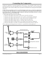
Complete the installation by connecting components as shown in Fig. . Excess harness should be neatly coiled
and secured with nylon ties. The components may have to be disconnected for service at some point during the
boats lifetime, so leave at least 4 inches (10 cm) of clearance in all directions for releasing and removing their
connectors.
Connecting the Components
Caution: Harnesses should be run as far as practical from high current wires or wiring runs and should not
be subject to water, fuels, lubricants, or excess heat . Electrical connectors should also be protected from rain,
spray, and wash down . When possible, install components with connectors pointing downward, or at least
angled downward, to protect them from drips .
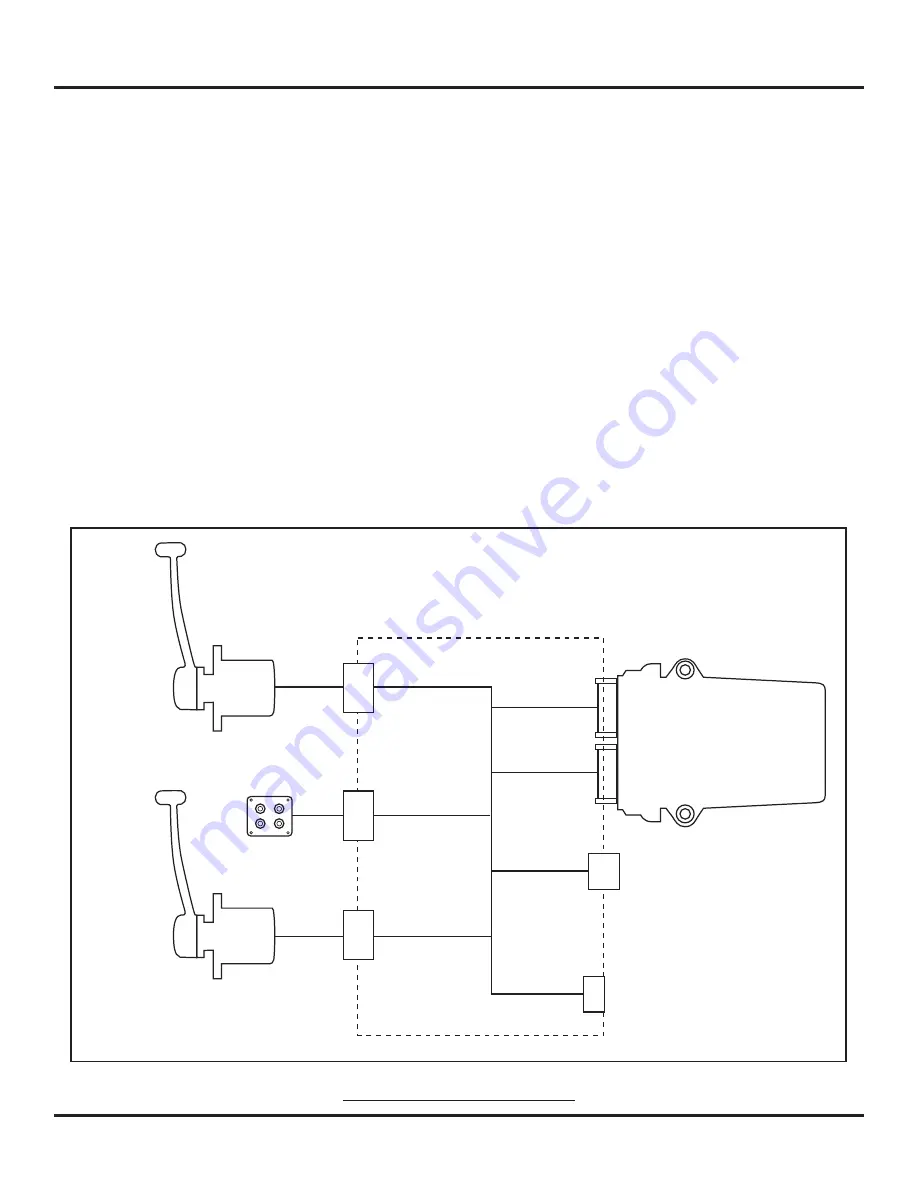
1. The CE41400 cable harness has seven connections:
a. Connect the cable marked “Port Control” to the connector on the Port control head.
b. Connect the cable marked “Starboard Control” to the connector on the Starboard control head.
c. Connect the cable marked “Operators Panel” to the connector on the CP100 Operator Panel.
d. Connect the cable marked “Gray Connector” to the gray outlet on the CH67019D.
e. Connect the cable marked “Black Connector” to the black outlet on the CH67019D.
f. Connect the cable marked “Trolling Switch” to the Trolling Switch Connections (if applicable).
g. Connect the cable marked “CAN Bus” to the NMEA 000 Connector/Main CAN Bus connection.
Refer to points a-g on the diagram below. Note that “xx” as in CE107xx is cable length in feet.
Figure 3: Connection Diagram
NMEA 2000 Connector
CH67019D
CE41600 Cable Harness
CP1900
Port
CP1900
Starboard
CP1200
Trolling Switch Connections
Port
Control
Operators
Panel
Starboard
Control
Gray
Connector
Black
Connector
Trolling
Switch
CAN Bus
a
b
d
e
f
g
c


