CL600 Operator's Manual
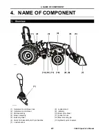
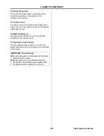
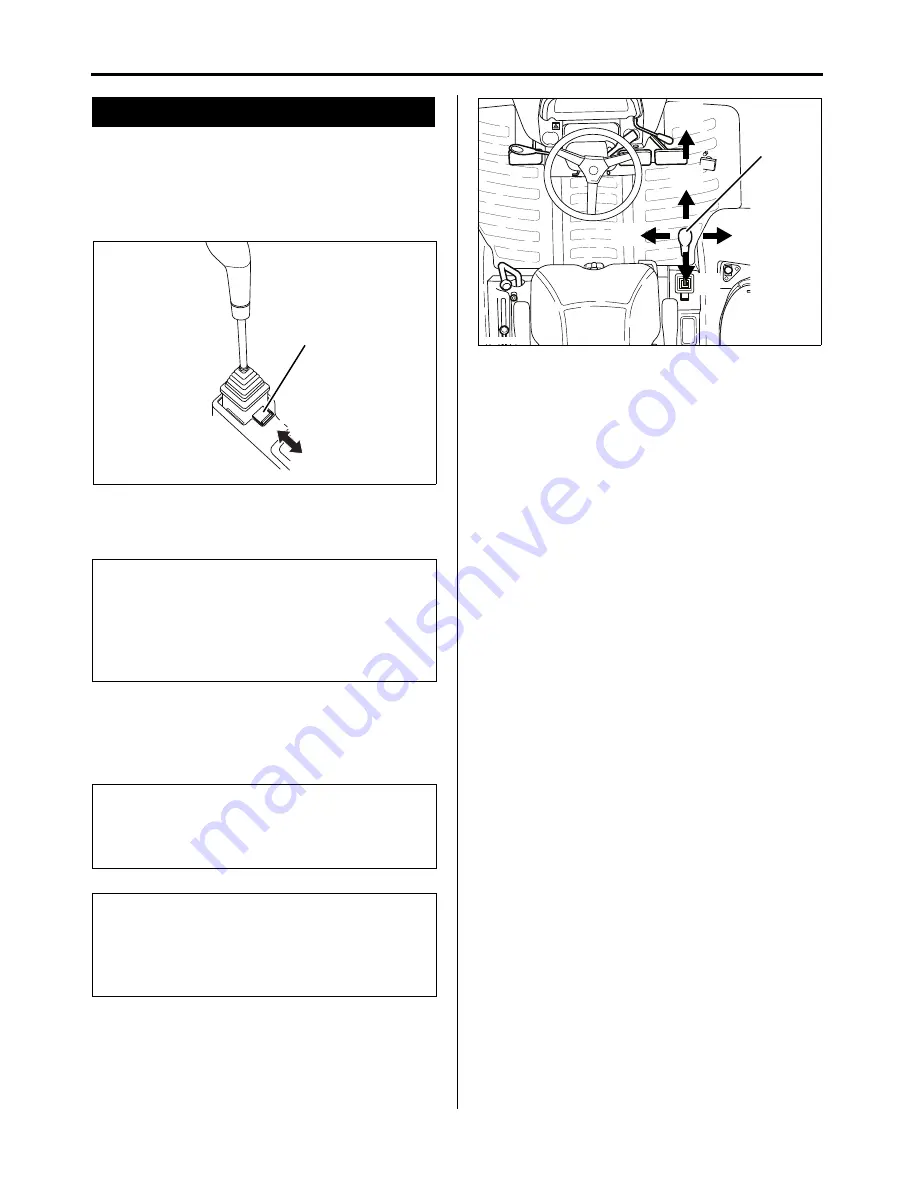
(1) Implement control lever lock
Use the implement control lever lock to lock the
implement control lever to the N (neutral) position.
The preceding procedure prevents accidental
operation of the loader.
.
(A) Implement control lever lock
(a) Locked position
(b) Unlocked position
(2) Implement control lever
Use the implement control lever to operate the
loader.
(A) Implement control lever
(a) Lower
(b) Float
(c) Dump
(d) Raise
(e) Curl
(3) Mast assembly
The mast assembly connects the boom assembly to
the loader mounts.
(4) Boom assembly
The boom assembly is the frame of the loader.
(5) Bucket cylinder
The bucket cylinder makes the bucket curl or dump,
depending on the position of the implement control
lever.
(6) Quick hitch assembly latch pin handles
Use to lock and unlock the loader bucket.
(7) Loader bucket
The loader bucket is for scooping, carrying and
dumping the load.
(8) Loader stand
Use the loader stand to support the loader when the
loader is stored away or separated from the tractor.
(9) Indicator
Use as guide for the loader bucket position.
2. Function of Components
IMPORTANT: Avoid damage!
●
After the implement control lever has been locked
with the implement control lever lock, move the
implement control lever with a light force.
●
The preceding operation ensure that the
implement control lever has been securely locked.
IMPORTANT: Avoid damage!
●
Do not attempt to operate the implement control
lever while the implement control lever lock is in
locked position.
NOTE
●
The implement control lever return to the
N (neutral) position when released except when
the implement control lever is in the float (b)
position.
(A)
(a)
(b)
450̲009̲ICLLock
P5‑3 top view 2
(b)
(a)
(c)
(e)
(A)
(d)
Summary of Contents for CL Series
Page 46: ...NOTE...


