background image

Checking and adjusting the spreader 


20 


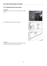
5-3. Checking the electrical system


<Checking> 

Confirm  that  the  harness  is  firmly  connected  with  the  main 

harness. 


Confirm that the harness is firmly fixed by clamps. 


[Reference] 

The alarm does not operate normally when the rotation sensor 

is defective or when the harness is not connected. 


Summary of Contents for CSS

Page 1: ...OPERATOR S MANUAL SPREADER CSS VNQ For Combine Harvester AW82V Original instructions en ...

Page 2: ...ty before using the product Contact your Yanmar dealer for any questions you have or anything you do not understand Notice Some parts may be modified to improve this product Some of the content photographs and diagrams in this operator s manual may be different from the actual product Notice of such modifications will not be provided We hope that there are no problems with this operator s manual I...

Page 3: ...ges in this operator s manual When you see this symbol carefully read the messages that follow 2 NOTE describes precautions to take while working IMPORTANT NOTE Measurements This spreader is of metric design All hardware are therefore metric ISO Make sure to use the specified metric hardware when service becomes necessary Direction Right hand and left hand sides of the spreader and combine harvest...

Page 4: ...6 Chapter 2 Part names 7 Chapter 3 Installing the spreader 8 3 1 Before installing the spreader 8 3 2 Installing the spreader 9 Chapter 4 Operating the spreader 15 4 1 Diffused operation 15 4 2 Centralized operation 16 Chapter 5 Checking and adjusting the spreader 17 5 1 Checking and adjusting the blades 18 5 2 Checking and adjusting the spreader drive belt 19 5 3 Checking the electrical system 20...

Page 5: ...y May result in serious injury if installed or removed by one person since the spreader weighs approximately 120kg In addition if the engine is not turned off during work it may result in serious injury 1 2 Precautions for using the spreader Always turn off the engine before removing clogged straw from the rotating blades and saw blades Failure to comply It may result in you coming into contact wi...

Page 6: ...ing caught in the machinery resulting in injury by the rotating parts Wear thick gloves when checking and replacing the blades Do not touch the cutting edge of the blades Failure to comply May result in you coming into contact with the blades resulting in injury 1 4 Machine identification plate location When the machine runs abnormally If an abnormality persists even after performing maintenance c...

Page 7: ...For your safety 6 1 5 Safety labels location 1 2 3 No Parts Number Parts name 1 1E6B35 97560 CAUTION install the cover 2 1E6B35 97540 CAUTION stop the engine 3 1E6B35 97650 WARNING rotation ...

Page 8: ...Part names 7 Chapter 2 Part names 1 Guide plate adjusting nut 2 Diffusion plate 3 Rotating blade 4 Guide plate 5 Saw blade ...

Page 9: ...oximately 120kg In addition if the engine is not turned off during work it may result in serious injury 3 1 Before installing the spreader 1 Remove the upper and lower rear covers of the threshing section a b as shown in the figure Reference The lower rear cover b does not need to be reattached after installing the spreader assembly Parts to remove Bolt M8 x 20 9 pcs Bolt M10 x 20 3 pcs Nut M8 2pc...

Page 10: ... 1 Attach the mounting bracket L directly onto the thresher as shown in the figure Parts for installation Bolt M8 x 25 6pcs 2 Attach the plate to the thresher frame at the rear of the combine harvester Parts for installation Nut M8 2pcs Spring washer 2pcs ...

Page 11: ...t there will be no space for the harness 4 Connect the terminal of the electrical sensor harness to the rotation sensor and fix the harness to the threshing section IMPORTANT The harness must be put through from the pivot If it is not put through the harness may interfere with the cutter belt As a result the harness may get caught and damaged The rotation sensor cable should be fed through the piv...

Page 12: ...move Nut M20 Collar 36 x 45 x 56 Spring washer Collar 21 x 64 x 10 Reference The collar 36 x 45 x 56 is not required once the pulley is installed 9 Install the spreader drive pulley to the winnower drive pulley shaft Parts for installation V pulley 298 C1 Nut M20 Spring washer Collar 21 x 64 x 10 10 Install the central belt pulley assembly to the left side of the thresher frame Parts for installat...

Page 13: ...2pcs Spring washer M8 2pcs Washer 2pcs Bolt M8 x 20 2pcs 13 Install the tension rod bracket to the left side of the thresher frame Parts for installation Tension pulley ASSY Nut M8 2pcs 14 Install the V belts between the central pulley to the spreader drive pulley then install the V belt between the winnower drive pulley and the central pulley Parts for installation V belt B86 H4 2pcs V belt SC101...

Page 14: ... M20 16 Install the tension bolts and tension springs Two places Tension for central pulley to spreader drive pulley Tension for winnower to central pulley 17 Adjust the length of the springs to 210 2 mm 1 Lock nut 2 Tension spring the winnower to the central pulley 3 Tension spring the central pulley to the spreader drive pulley ...

Page 15: ...d line in the figure so that the cover does not interfere with the spreader drive belts 19 Attach the spreader cover 20 Attach the upper rear cover At this time tighten the clamp with bolts on the right side and fix the harness that is connected to the spreader rotation sensor 21 Close the side cover of the threshing section ...

Page 16: ... a time Failure to comply May result in you coming into contact with the blades resulting in injury Always turn off the engine before adjusting the spreader Do not put your hands into the spreader Failure to comply May result in you coming into contact with blades resulting in injury Do not sit or stand on the diffusion plate Failure to comply May result in the diffusion plate becoming deformed re...

Page 17: ...Operating the spreader 16 4 2 Centralized operation 1 Loosen the nuts 3pcs 2 Move the bolt to the Centralized position and then tighten the nuts to fix the bolt in position ...

Page 18: ...enance Failure to comply May result in clothes getting caught in the machinery resulting in injury by the rotating parts Wear thick gloves when checking and replacing the blades Do not touch the cutting edge of the blades Failure to comply May result in you coming into contact with the blades resulting in injury IMPORTANT Do not use worn blades in order to guarantee balanced rotation Use Yanmar ge...

Page 19: ...ke sure there are no gaps between the stay and bracket 1 Blade stay 2 Bolt 3 Replace the other saw blades in the same way Power to the spreader must be turned off when replacing the blades Replacing the rotating blades 1 When replacing the rotating blades 2 place a wooden block 3 under the saw blades to stop the rotating blades from rotating Place the wooden block in a position opposite to the dir...

Page 20: ...me way Power to the spreader must be turned off when replacing the rotating blades 5 2 Checking and adjusting the spreader drive belt Checking Be sure to adjust the length of the springs that are connected to the tension rod Adjusting Use adjusting nuts to adjust the length and fix the springs 1 Lock nut 2 Tension spring the winnower to the central pulley 3 Tension spring the central pulley to the...

Page 21: ...trical system Checking Confirm that the harness is firmly connected with the main harness Confirm that the harness is firmly fixed by clamps Reference The alarm does not operate normally when the rotation sensor is defective or when the harness is not connected ...

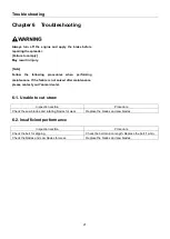
Page 22: ... the failure is not solved after maintenance please contact your Yanmar dealer 6 1 Unable to cut straw Inspection section Procedure Check the saw blades and rotating blades for wear Replace the blades and saw blades 6 2 Insufficient performance Inspection section Procedure Check the belt for slipping Check the belt tension length Replace the belt if worn Check the blades and saw blades for wear Re...

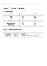
Page 23: ...eed rpm 2833 Diameter mm 446 Circumferential velocity m s 66 1 Length of blade mm 120 Number of blades 24 7 2 List of main consumable parts Part number Name Remarks 1 1S7596 32201 Blade T5 Rotating blade 2 1S7596 36400 Blade Saw blade 3 25124 010504 LC105 AG8 V belt from winnower pulley to central pulley 4 25123 008604 LB86 AG8 V belt from central pulley to spreader drive pulley ...

Reviews: