3 ENGINE
3 ENGINE
EF494T TM 06/2011 edition
97
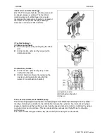
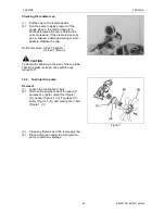
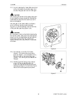
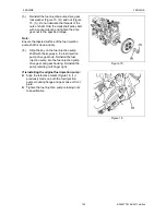
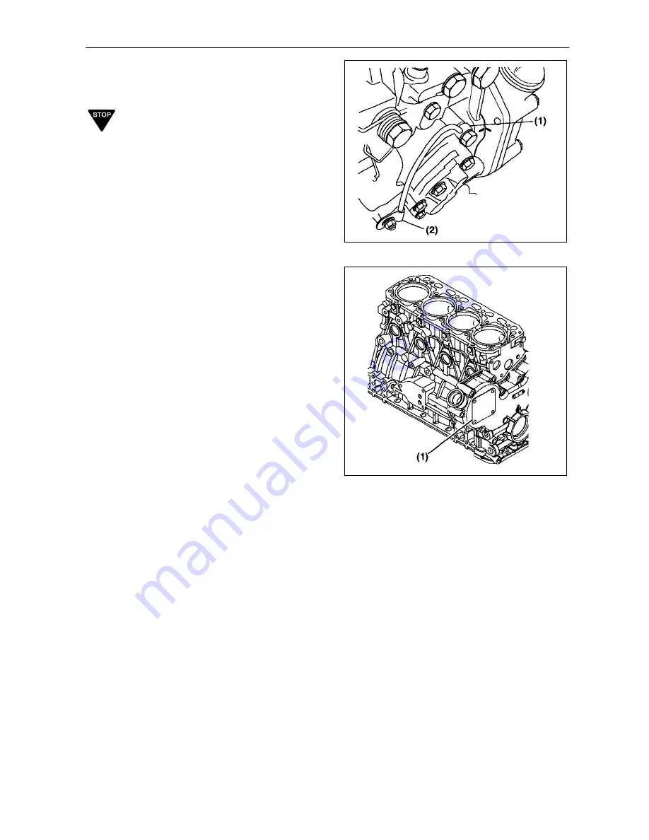
(14) Disconnect the lube oil line (Figure 4, (1))
and the clamp (Figure 4, (2)) from the
pump.
IMPORTANT
Take care to not damage or bend the oil line. In
some applications, it may be preferable to
remove the complete oil line assembly from the
engine before proceeding.
Figure 4
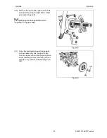
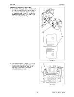
(15) Remove the fuel injection pump drive gear
cover (Figure 5, (1)).
Note:
The fuel injection pump drive gear cover is
secured with an adhesive sealant. Use a
gasket scraper to separate the fuel injection
pump cover from the gear case cover.
The fuel injection pump drive gear cover is
retained to the gear case cover by 4 bolts.
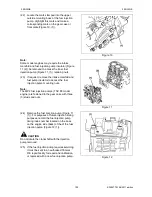
(16) To position the fuel/injection pump for
easier removal and installation, install a
dial indicator into the injection pump
plunger opening. Using a wrench on the
crankshaft pulley bolt, rotate the crankshaft
until the dial indicator shows that injection
pump plunger is at the bottom of it's stroke.
Figure 5
Summary of Contents for EF-494T
Page 1: ...EF494T TM 06 2011 edition ...
Page 85: ...3 ENGINE 3 ENGINE EF494T TM 06 2011 edition 77 3 ENGINE ...
Page 88: ...3 ENGINE 3 ENGINE EF494T TM 06 2011 edition 80 B Return ...
Page 126: ...4 CLUTCH 4 CLUTCH EF494T TM 06 2011 edition 118 4 CLUTCH ...
Page 130: ...4 CLUTCH 4 CLUTCH EF494T TM 06 2011 edition 122 ...
Page 133: ...5 TRANSMISSION 5 TRANSMISSION EF494T TM 06 2011 edition 125 5 TRANMISSION ...
Page 167: ...7 FRONT AXLE 7 FRONT AXLE EF494T TM 06 2011 edition 159 7 FRONT AXLE ...
Page 169: ...7 FRONT AXLE 7 FRONT AXLE EF494T TM 06 2011 edition 161 7 2 CROSS SECTION VIEW ...
Page 176: ...8 POWER STEERING 8 POWER STEERING EF494T TM 06 2011 edition 168 8 POWER STEERING ...
Page 234: ...11 APPENDIXES 11 APPENDIXES EF494T TM 06 2011 edition 226 11 APPENDIXES ...
Page 235: ...11 APPENDIXES 11 APPENDIXES EF494T TM 06 2011 edition 227 11 1 HYDRAULIC CIRCUIT DIAGRAM ...
Page 236: ...228 11 2 ELECTRICAL CIRCUIT DIAGRAM 11 2 1 WIRING HARNESS ...
Page 238: ...230 11 2 3 ELECTRICAL WIRING DIAGRAM ...
Page 239: ......

