3 ENGINE
3 ENGINE
EF494T TM 06/2011 edition
103
(5)
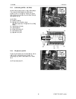
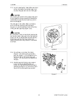
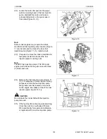
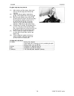
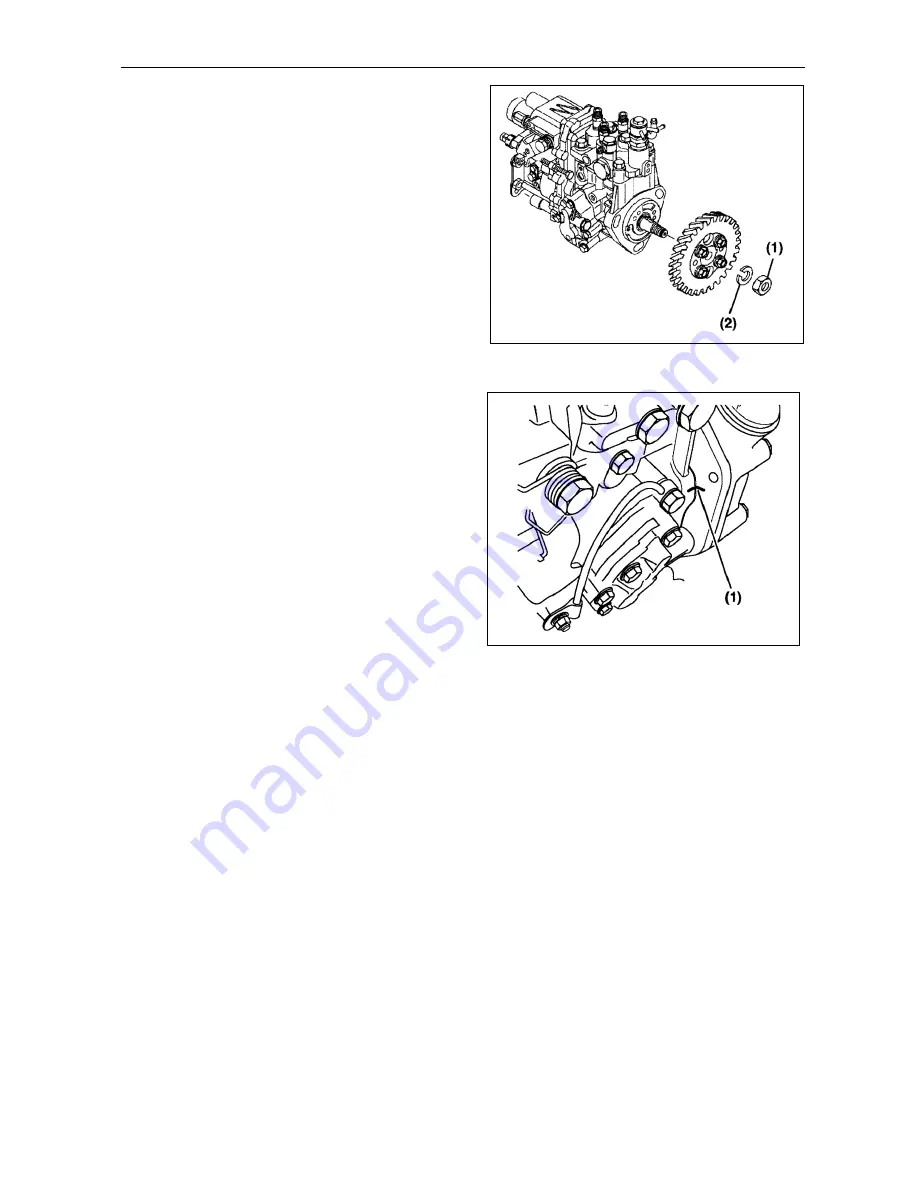
Reinstall the fuel injection pump drive gear
lock washer (Figure 15, (2)) and nut (Figure
15, (1)). Do not lubricate the threads of the
nuts or shaft. Hold the crankshaft pulley bolt
with a socket wrench and tighten the drive
gear nut to the specified torque.
Note:
Ensure the tapered surface of the fuel injection
pump shaft is clean and dry.
(6)
Align the key on the fuel injection pump
shaft with the keyway in the fuel injection
pump drive gear hub. Reinstall the fuel
injection pump into the fuel injection pump
drive gear and gear housing. Reinstall the
pump retaining nuts finger tight.
Figure 15
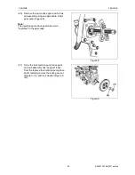
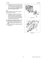
If reinstalling the original fuel injection pump:
Align the reference marks (Figure 16, (1))
previously made on both the fuel injection
pump mounting flange and gear case or front
plate.
Tighten the fuel injection pump retaining nuts
to specification.
Figure 16
Summary of Contents for EF-494T
Page 1: ...EF494T TM 06 2011 edition ...
Page 85: ...3 ENGINE 3 ENGINE EF494T TM 06 2011 edition 77 3 ENGINE ...
Page 88: ...3 ENGINE 3 ENGINE EF494T TM 06 2011 edition 80 B Return ...
Page 126: ...4 CLUTCH 4 CLUTCH EF494T TM 06 2011 edition 118 4 CLUTCH ...
Page 130: ...4 CLUTCH 4 CLUTCH EF494T TM 06 2011 edition 122 ...
Page 133: ...5 TRANSMISSION 5 TRANSMISSION EF494T TM 06 2011 edition 125 5 TRANMISSION ...
Page 167: ...7 FRONT AXLE 7 FRONT AXLE EF494T TM 06 2011 edition 159 7 FRONT AXLE ...
Page 169: ...7 FRONT AXLE 7 FRONT AXLE EF494T TM 06 2011 edition 161 7 2 CROSS SECTION VIEW ...
Page 176: ...8 POWER STEERING 8 POWER STEERING EF494T TM 06 2011 edition 168 8 POWER STEERING ...
Page 234: ...11 APPENDIXES 11 APPENDIXES EF494T TM 06 2011 edition 226 11 APPENDIXES ...
Page 235: ...11 APPENDIXES 11 APPENDIXES EF494T TM 06 2011 edition 227 11 1 HYDRAULIC CIRCUIT DIAGRAM ...
Page 236: ...228 11 2 ELECTRICAL CIRCUIT DIAGRAM 11 2 1 WIRING HARNESS ...
Page 238: ...230 11 2 3 ELECTRICAL WIRING DIAGRAM ...
Page 239: ......

