3 ENGINE
3 ENGINE
EF494T TM 06/2011 edition
107
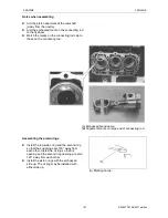
Notes when assembling
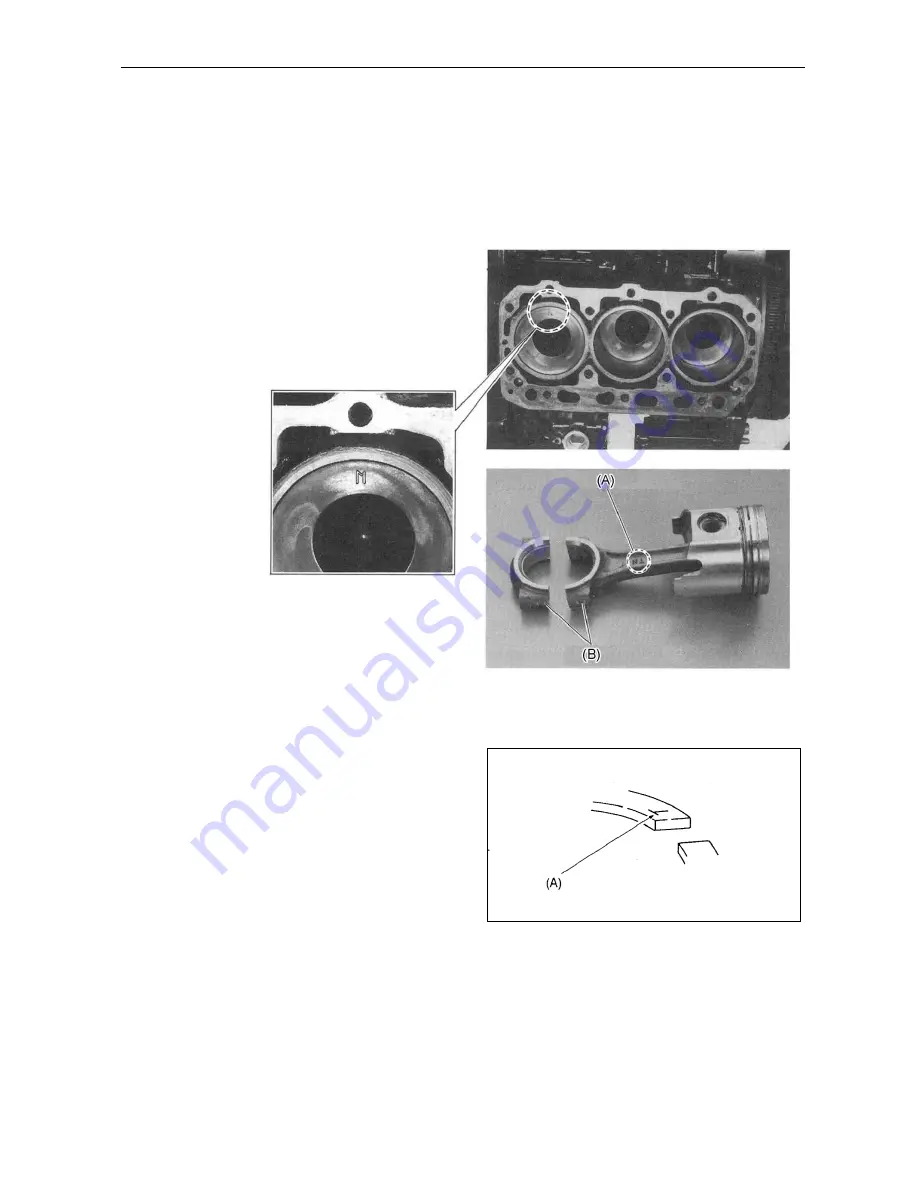
Aim the piston seal mark at the camshaft
(away from the nozzle).
Aim the embossed mark on the connecting rod
to the flywheel.
Match the marks on the connecting rod cap to
those on the connecting rod.
(A) Embossed brand name
(B) Alignment marks on large end of connecting rod
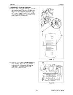
Assembling the piston rings
Install the top piston ring and the second ring
so that their openings are 120° away from
each other. Install the oil ring so that its
opening and the second ring opening are also
120° away from each other.
Install the piston rings with the embossed
side up. The oil ring may be installed with
either side up.
(A) Marking on top.
Summary of Contents for EF-494T
Page 1: ...EF494T TM 06 2011 edition ...
Page 85: ...3 ENGINE 3 ENGINE EF494T TM 06 2011 edition 77 3 ENGINE ...
Page 88: ...3 ENGINE 3 ENGINE EF494T TM 06 2011 edition 80 B Return ...
Page 126: ...4 CLUTCH 4 CLUTCH EF494T TM 06 2011 edition 118 4 CLUTCH ...
Page 130: ...4 CLUTCH 4 CLUTCH EF494T TM 06 2011 edition 122 ...
Page 133: ...5 TRANSMISSION 5 TRANSMISSION EF494T TM 06 2011 edition 125 5 TRANMISSION ...
Page 167: ...7 FRONT AXLE 7 FRONT AXLE EF494T TM 06 2011 edition 159 7 FRONT AXLE ...
Page 169: ...7 FRONT AXLE 7 FRONT AXLE EF494T TM 06 2011 edition 161 7 2 CROSS SECTION VIEW ...
Page 176: ...8 POWER STEERING 8 POWER STEERING EF494T TM 06 2011 edition 168 8 POWER STEERING ...
Page 234: ...11 APPENDIXES 11 APPENDIXES EF494T TM 06 2011 edition 226 11 APPENDIXES ...
Page 235: ...11 APPENDIXES 11 APPENDIXES EF494T TM 06 2011 edition 227 11 1 HYDRAULIC CIRCUIT DIAGRAM ...
Page 236: ...228 11 2 ELECTRICAL CIRCUIT DIAGRAM 11 2 1 WIRING HARNESS ...
Page 238: ...230 11 2 3 ELECTRICAL WIRING DIAGRAM ...
Page 239: ......

