7 FRONT AXLE
7 FRONT AXLE
EF494T TM 06/2011 edition
162
7.3 FRONT WHEEL ALIGNMENT
The tractor front wheels have a certain angle in
the lateral and back-and-forth direction for easy
steering performance; reliability, safety, stability
and linearity of motion; and reduction of tire
wearing.
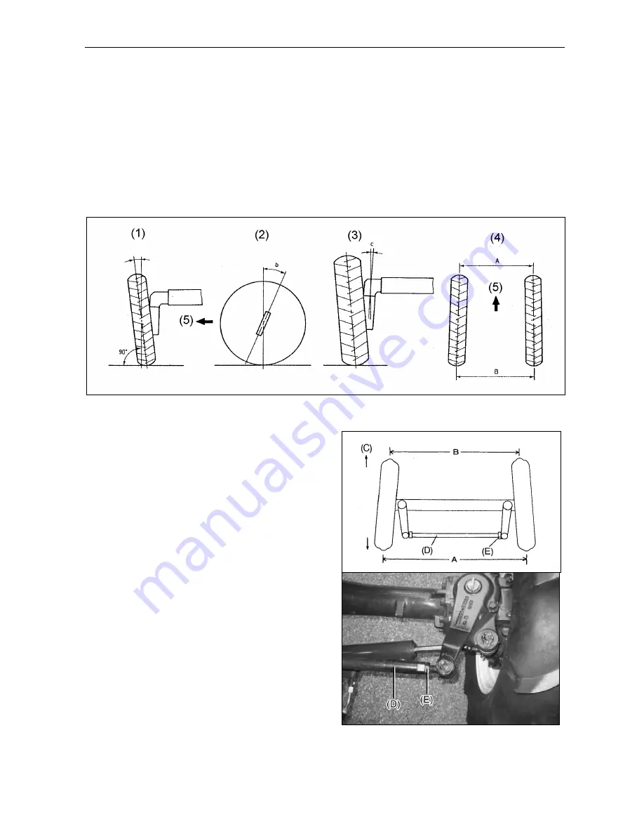
This is called "front wheel alignment" and
includes the following 4 factors:
(1) Camber angle, a: 2°
(2) Caster angle, b: 0°
(3) Kingpin tilt, c: 12°
(4) Toe-in, B-A: 4-8 mm
(5) Traveling direction
These factors are shown below:
Note: (1), (2), and (3) cannot be adjusted.
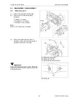
Adjusting the toe-in
If the steering response is irregular or subject to
vibration, check the toe-in. Toe-in is the
arrangement in which the front wheels are
oriented slightly inward so that the distance
between the front edges of the wheels (A) is
slightly smaller than the distance between the
rear edges (B). The toe-in (difference) should be
4-8 mm. If it is not within this range, adjust the
toe-in as described below:
(1)
Loosen the locknuts at the ends of the tie
rod.
(2)
Turn tie rod A until the toe-in is 4-8 mm.
(3)
When the toe-in is 4-8 mm, tighten the
locknuts.
(C) Front
(D) Tie rod
(E) Lockout
Summary of Contents for EF-494T
Page 1: ...EF494T TM 06 2011 edition ...
Page 85: ...3 ENGINE 3 ENGINE EF494T TM 06 2011 edition 77 3 ENGINE ...
Page 88: ...3 ENGINE 3 ENGINE EF494T TM 06 2011 edition 80 B Return ...
Page 126: ...4 CLUTCH 4 CLUTCH EF494T TM 06 2011 edition 118 4 CLUTCH ...
Page 130: ...4 CLUTCH 4 CLUTCH EF494T TM 06 2011 edition 122 ...
Page 133: ...5 TRANSMISSION 5 TRANSMISSION EF494T TM 06 2011 edition 125 5 TRANMISSION ...
Page 167: ...7 FRONT AXLE 7 FRONT AXLE EF494T TM 06 2011 edition 159 7 FRONT AXLE ...
Page 169: ...7 FRONT AXLE 7 FRONT AXLE EF494T TM 06 2011 edition 161 7 2 CROSS SECTION VIEW ...
Page 176: ...8 POWER STEERING 8 POWER STEERING EF494T TM 06 2011 edition 168 8 POWER STEERING ...
Page 234: ...11 APPENDIXES 11 APPENDIXES EF494T TM 06 2011 edition 226 11 APPENDIXES ...
Page 235: ...11 APPENDIXES 11 APPENDIXES EF494T TM 06 2011 edition 227 11 1 HYDRAULIC CIRCUIT DIAGRAM ...
Page 236: ...228 11 2 ELECTRICAL CIRCUIT DIAGRAM 11 2 1 WIRING HARNESS ...
Page 238: ...230 11 2 3 ELECTRICAL WIRING DIAGRAM ...
Page 239: ......

