9 HYDRAULIC LIFT UNIT
9 HYDRAULIC LIFT UNIT
EF494T TM 06/2011 edition
198
9.3.3
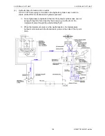
Hydraulic pressure flow
(1)
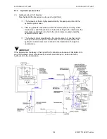
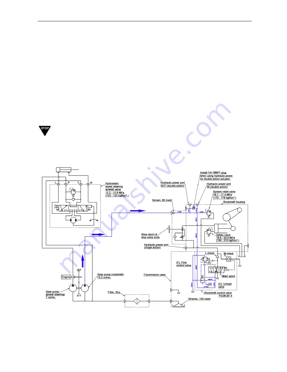
Hydraulic circuit, 3-P, Neutral
New hydraulic lift units are set up to use a 3-point hitch.
①
The hydraulic oil that is highly pressurized by the gear pump is fed to the
hydraulic cylinder case.
↓
②
After any particles have been removed from the hydraulic oil using an 80-
mesh screen, and if the pressure is below the setting for the relief valve, the
high-pressure hydraulic oil is fed to the control valve mounted under the
hydraulic cylinder case.
↓
③
The hydraulic circuit is switched by the control valve, to move the 3-point
hitch up and down. When the control valve is in the neutral position, the
hydraulic oil under pressure is returned to the transmission through the
unload valve.
IMPORTANT
If the implement is too heavy or the 3-point hitch cannot move because of obstacles in its
way, the hydraulic circuit is protected by a relief valve that opens, which returns the
hydraulic oil to the transmission.
Summary of Contents for EF-494T
Page 1: ...EF494T TM 06 2011 edition ...
Page 85: ...3 ENGINE 3 ENGINE EF494T TM 06 2011 edition 77 3 ENGINE ...
Page 88: ...3 ENGINE 3 ENGINE EF494T TM 06 2011 edition 80 B Return ...
Page 126: ...4 CLUTCH 4 CLUTCH EF494T TM 06 2011 edition 118 4 CLUTCH ...
Page 130: ...4 CLUTCH 4 CLUTCH EF494T TM 06 2011 edition 122 ...
Page 133: ...5 TRANSMISSION 5 TRANSMISSION EF494T TM 06 2011 edition 125 5 TRANMISSION ...
Page 167: ...7 FRONT AXLE 7 FRONT AXLE EF494T TM 06 2011 edition 159 7 FRONT AXLE ...
Page 169: ...7 FRONT AXLE 7 FRONT AXLE EF494T TM 06 2011 edition 161 7 2 CROSS SECTION VIEW ...
Page 176: ...8 POWER STEERING 8 POWER STEERING EF494T TM 06 2011 edition 168 8 POWER STEERING ...
Page 234: ...11 APPENDIXES 11 APPENDIXES EF494T TM 06 2011 edition 226 11 APPENDIXES ...
Page 235: ...11 APPENDIXES 11 APPENDIXES EF494T TM 06 2011 edition 227 11 1 HYDRAULIC CIRCUIT DIAGRAM ...
Page 236: ...228 11 2 ELECTRICAL CIRCUIT DIAGRAM 11 2 1 WIRING HARNESS ...
Page 238: ...230 11 2 3 ELECTRICAL WIRING DIAGRAM ...
Page 239: ......


