2 DISASSEMBLY OF COMPONENTS
2 DISASSEMBLY OF COMPONENTS
EF494T TM 06/2011 edition
52
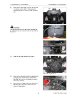
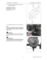
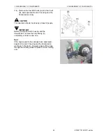
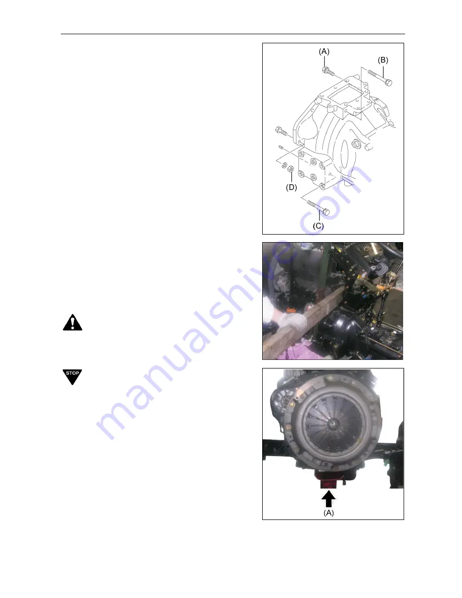
(16) Remove nuts and bolts that connect engine
and clutch housing.
(A) Bolt M12x30: 3 pieces.
(B) Bolt M12x170: 2 pieces.
(C) Bolt M12x100: 2 pieces.
(D) Nut M12: 1 pc.
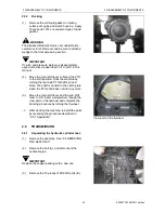
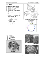
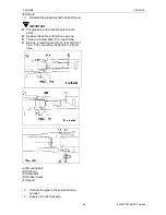
(17) Separate the engine and the clutch housing.
Note:
If clutch housing adhered to engine by liquid gasket
too strongly, place a piece of wood as right photo
shows and push or tap on it lightly. It will be easy to
separate them.
WARNING
Be careful transmission not to come off supporting
jack. This operation should be done by at least 2
people.
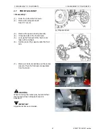
IMPORTANT
After separating, put a rigid stand to section A and
remove the lifting bolt. If not, the lifting bolt may be
deformed and you may not be able to remove it.
Summary of Contents for EF-494T
Page 1: ...EF494T TM 06 2011 edition ...
Page 85: ...3 ENGINE 3 ENGINE EF494T TM 06 2011 edition 77 3 ENGINE ...
Page 88: ...3 ENGINE 3 ENGINE EF494T TM 06 2011 edition 80 B Return ...
Page 126: ...4 CLUTCH 4 CLUTCH EF494T TM 06 2011 edition 118 4 CLUTCH ...
Page 130: ...4 CLUTCH 4 CLUTCH EF494T TM 06 2011 edition 122 ...
Page 133: ...5 TRANSMISSION 5 TRANSMISSION EF494T TM 06 2011 edition 125 5 TRANMISSION ...
Page 167: ...7 FRONT AXLE 7 FRONT AXLE EF494T TM 06 2011 edition 159 7 FRONT AXLE ...
Page 169: ...7 FRONT AXLE 7 FRONT AXLE EF494T TM 06 2011 edition 161 7 2 CROSS SECTION VIEW ...
Page 176: ...8 POWER STEERING 8 POWER STEERING EF494T TM 06 2011 edition 168 8 POWER STEERING ...
Page 234: ...11 APPENDIXES 11 APPENDIXES EF494T TM 06 2011 edition 226 11 APPENDIXES ...
Page 235: ...11 APPENDIXES 11 APPENDIXES EF494T TM 06 2011 edition 227 11 1 HYDRAULIC CIRCUIT DIAGRAM ...
Page 236: ...228 11 2 ELECTRICAL CIRCUIT DIAGRAM 11 2 1 WIRING HARNESS ...
Page 238: ...230 11 2 3 ELECTRICAL WIRING DIAGRAM ...
Page 239: ......


