background image

Page  8 

© Yanmar 2008


Electronic Control System:  

Operation Manual for SY Series Engines with GEN III Controls 

Appendix A

Quad screen Parameters

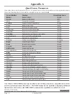
These data choices can be placed in any box of a quad screen or in the two small boxes of an engine data screen.


The screen headings that are included in a standard set-up are noted in 

bold

.

screen Heading 

function 

typical Data source

Battery


Battery Voltage 

Engine

Bearing 

Bearing to Waypoint 

GPS

COG 

Course Over Ground 

GPS

Coolant


Engine Coolant Temperature 

Engine

Depth 

Depth of the water 

Sonar

Fuel 

Fuel level if single engine 

Sender

Fuel Center 

Fuel Level in the center tank 

Sender

Fuel Port


Fuel Level in the port tank 

Sender

Fuel Rate


Instantaneous fuel burn rate per engine 

Engine

Fuel Starboard 

Fuel Level in the starboard tank 

Sender

Gear 

Indicates the selected gear 

Engine

Heading 

Current vessel heading 

Compass

Hours


Actual Engine Hours 

Engine

Load


Percent load on engine 

Engine

Network 

Network voltage 

Engine

Oil Pressure


Engine Oil Pressure 

Engine

Oil Temperature 

Engine Oil Temperature 

Engine

RPM


Engine Revolutions Per Minute 

Engine

Rudder 

Rudder Angle 

Sender

Sea Temp 

Sea Water Temperature 

Sender

SOG 

Speed Over Ground 

GPS

Speed (SOW) 

Speed through the water 

Sender

Tab Port 

Position of the Port Trim Tab 

Sender

Tab Stbd 

Position of the Starboard Trim Tab 

Sender

Throttle


The percent of throttle currently selected 

Engine

Torque


The percent torque the engine is developing 

Engine

Turbo


The amount of turbo boost pressure 

Engine

Waste 

The amount of waste in the holding tank 

Sender

Water 

The amount of water in the water tank 

Sender

WP Dist 

The distance to the selected waypoint 

GPS

XTE 

The cross track error from a best source 

GPS

Note: Data in NMEA 2000® format may be added to the CANBus system from a compatible device which 

feeds the optional parameters listed above.  The i5601E display has the capability of displaying additional 

information as other devices with NMEA 2000® communication capabilities are added to the vessel.

Summary of Contents for i8350

Page 1: ...Electronic Control System Operation Manual for SY Series Engines with GEN III Controls ELECTRONIC CONTROL SYSTEM MANOPSY3m01 Revision 3 2 ...

Page 2: ...ng with exercising care and using common sense when performing such actions Maximum performance and compliance with the EMC Directive can only be ensured by correct installation It is strongly recommended that the installation conforms with the following standards APPLICABLE STANDARDS a ISO 8846 Small Craft Electrical Devices Protection against ignition of surrounding flammable gases b ISO Interna...

Page 3: ...Sync Operations 9 Cruise Sync CS 9 Power Train Sync PTS 9 Trolling Mode option 10 i5601E Digital Display Alarms Diagnostic Code Screens 11 Engine Alarms 12 Engine Diagnostic Codes 12 Maintenance Warning 12 Power Reduction Mode 12 Diagnostics 13 System Alarms 13 i8350 55 Operation 14 Appendix A i5601E Digital Display Setup 15 Display Settings 16 Menus 16 User Settings and Factory Settings 17 Unlock...

Page 4: ...cian Shift Throttle Control Head The Shift Throttle Control Head selects the gear positions and the throttle settings The Control Head has several lights that confirm modes of operation and display warnings if present Buttons enable engine RPM synchronization and shift disconnect as well as setting the brightness of the lights Other control configurations with the same functions but different form...

Page 5: ...m mounted shift throttle control head and the engine the system is designed to revert to the redundant or back up throttle First the engine would reduce rpms to idle speed the digital display would show Throttle Error and a small red indicator light would flash at the key panel or switch panel Near the red light is a small potentiometer looks like a volume control knob Turn the knob all the way to...

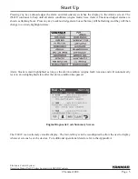
Page 6: ...tion to take Press Any Key To Continue These screens show all of the key engine data and can be accessed by pushing a single button The right most button allows the contrast and brightness to be set see illustration below Start Up i5601E Digital Display When powered up the i5601E Digital Display will initially display an introductory screen showing the software revision level It will then display ...

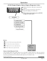
Page 7: ...y key to acknowledge alarm boxes that may still be flashing and they will then change to a steady highlighted state Start Up Engine Diagnostic Code Summary Screen The i5601E is an extremely versatile display The four left keys can be reconfigured to allow the user to display whatever screens he or she desires For additional operational details refer to the Appendix A Alarm blocks remain highlighte...

Page 8: ... The green control head light will illuminate a Check to see if the green light on the control head is solid or flashing If solid proceed to the next step If flashing push the Select button to select the head Position the control lever to neutral and the yellow light will now come on The Shift Throttle Control Head selects the gear positions and the throttle settings The Control Head has several l...

Page 9: ...tes a station is active On single station boats station selection is automatic For multi station boats choose a station and then press SELECT button with levers in neutral to Change Stations Move to new station and press select button Green lamp flashes Match control handle positions with those of active station Green lamp goes steady when levers match and this station is now in control Engine Tri...

Page 10: ...N Neutral lamp can indicate status of either Shift Disconnect SD or Split Range Throttle SRT Please exercise caution when engaging disengaging either of these modes A steady on Neutral lamp ALWAYS indicates engine is in NEUTRAL Split Range Throttle SRT Flashing yellow N Neutral lamp SRT engaged for this engine Provides greater throttle sensitivity moving an engine s control lever to Full Forward w...

Page 11: ...note Your system ships with Cruise Sync set as the default Power Train Sync may be selected using the i5601E display Cruise Sync CS Default Automatically synchronizes engine RPMs when levers are close together and above 20 forward throttle A lit red SYNC lamp indicates sync is enabled TO ENable CS Press SYNC button Red lamp flashes Match control handle positions within 5 of each other Red lamp goe...

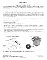
Page 12: ...g 40 lever movement used for throttle control to a maximum of 40 throttle The trolling defaults as shown in Appendix C can be set to a variety of operating modes Contact your dealer for details or see technical manual How to Enter Trolling Mode 1 Move the Control Head lever s to the Neutral position 2 Start the engine s if necessary The system must see RPM in order to permit trolling mode to be en...

Page 13: ...as a dedicated hot key is not required to view these screens User can hold Right most key down go into the menu mode and then via this menu access the desired screen Performs the function indicated by a pop up menu if present With no pop up menu showing briefly press to display the Lighting Contrast menu With no pop up menu showing press and HOLD to display the MAIN MENU Buttons Down Arrow moves m...

Page 14: ...o User Settings Press the right arrow button to enter the User Setting menu The arrow should be at the Reset Maint Time selection Press the right arrow key to reset The warning will go away When 250 hours of operation after the reset has occurred the maintenance warning will be displayed again This will occur every 250 hours thereafter This a reminder that periodic maintenance must be performed at...

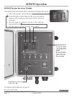
Page 15: ... various rates to indicate the following Operation Engine control unit status BLUE J1939 canbus operation yellow nmea2000 canbus operation GREEN If any of these are not flashing consult your dealer i8350 55 Engine Control Unit Critical Alarms Continuous flashing both lights on either side of the control indicates a Critical Alarm System will do a Safe Shut Down and must be serviced before further ...

Page 16: ...ion switch at the helm Tostarttheengine turnonEmergencyStartPowerbypressing in the top of the Emergency Start Power Switch The buzzer will sound Start the engine by pressing in the top of the Emergency Engine Start Switch Stop the engine by pressing the red Stop button For indicator light information see page 13 Programming connector Factory use only Important Note No service items exist behind th...

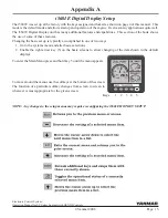
Page 17: ...e use of some of these features Changing the basic set up is typically accomplished in one of two ways 1 Go to the systems menu and alter basic selections 2 Enable the right arrow key 5 on the basic screens to allow changing of the data shown in the default displays To enter the Main Menu press and hold key 5 until the menu appears To move around the menus use the softkeys at the bottom of the scr...

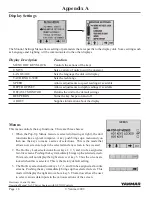
Page 18: ...pplies information about the display Menus This menu controls the key functions There are three choices 1 When the Pop Up Menus feature is selected drawing at right the unit functions like a typical computer A key push brings up a menu and you then use the keys to make a series of selections This is the mode that allows new screen set ups to be selected and any screen to be accessed 2 The Hot Key ...

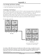
Page 19: ...n any key is pressed The Right Arrow button changes the menu to allow selection of each block Pressing a block key will cycle through the choices listed on the next page The choices are presented in alphabetical order Bold items are the default settings and will appear initially unless replaced by an indented item listed underneath Note Data in NMEA 2000 format may be added to the CANBus system fr...

Page 20: ...ngine Load Percent load on engine Engine Network Network voltage Engine Oil Pressure Engine Oil Pressure Engine Oil Temperature Engine Oil Temperature Engine RPM Engine Revolutions Per Minute Engine Rudder Rudder Angle Sender Sea Temp Sea Water Temperature Sender SOG Speed Over Ground GPS Speed SOW Speed through the water Sender Tab Port Position of the Port Trim Tab Sender Tab Stbd Position of th...

Page 21: ...gage Dly 0 0 Set Idle rpm Sync Pwr Train Setup TROLL Valve Fixed Shift Dly 0 0 Lead Eng Port SYSTEM SELECT AUTO ALARMs DIAGs Diag Codes Alarms Network Status Network Nodes MONITOR SETTINGS HOT KEYS LOCK Depth Offset Language Menu Units Menu SPEED Tach Range 0 3000 Default Monitor About Beeper ON MAIN MENU Appendix B i5601E Menu Navigation Performs the function indicated by a pop up menu if present...

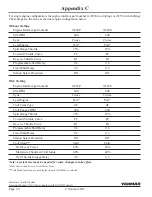
Page 22: ...t Delay 9 6 9 6 Fixed Shift Delay 0 2 0 2 Station Select Protection Off Off With Trolling Engine Interface part number i8355P i8355S Idle RPM 600 600 Sync Cruise Cruise Lead Engine Port Port Troll Trans Type ZF ZF Troll Engage RPM 800 800 Split Range Throttle 25 25 Forward Throttle Curve F8 F8 Reverse Throttle Curve R1 R1 Programmable Shift Delay 9 6 9 6 Fixed Shift Delay 0 2 0 2 Station Select Pr...

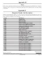
Page 23: ...on details with the Y code before notifying your Yanmar service technician Y Value Text Message Y0011 OVERREVING Y0012 SPEED SENSOR 1 Y0013 SPEED SENSOR 2 Y0014 WATER TEMPERATURE SENSOR Y0015 CHARGE AIR TEMPERATURE SENSOR Y0016 CHARGE AIR PRESSURE SENSOR Y0018 OIL PRESSURE SENSOR Y0023 FAULT IN i8350 MODULE Y0025 THROTTLE FAULT Y0027 EMERGENCY STOP OVERRIDE Y0028 OIL PRESSURE SHUT OFF Y0031 OIL PR...

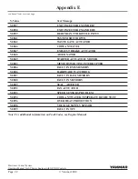
Page 24: ... Y0067 EXHAUST BRAKE ACTUATOR Y0068 ALTERNATOR Y0069 STARTER ACTUATOR MOTOR Y0083 MEMORY WRITING INTERRUPTED Y0084 FAULT IN EMS MEMORY Y0086 HARDWARE WATCHDOG Y0087 FAULT IN RAM MEMORY Y0088 FAULT IN MEMORY Y0089 SEAL ALTERED Y0092 FAN ACTUATOR Y0093 SPEED SENSORS PROBLEM Y0094 COOLANT WATER TEMPERATURE SHUTOFF Y0096 OVER HEAT PROTECTION Y0098 VOLTAGE SUPPLY SENSOR Y0099 FAULT IN TPU Appendix E co...

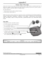
Page 25: ...station retains controls of the boat Operation To change stations this is the button sequence Go to the station you wish to make active Press the Select button Press the Select button again Press the Neutral or N button Press the Select button The station will go active green light on solid if the handles are matched with the originally active station Ifthegreenlightflashes matchthehandleswiththeo...

Page 26: ...play shows Yanmar and Teleflex units that have claimed an address on the bus From the information in the claimed message name Device Class Function and Instance Fields the type of Model number of the unit will be determined The specific model may not be indicated but it will give a general model of the type of the unit i e i813x The information displayed consists of Node Address Manufacturer s Cod...

Page 27: ...ax 31 36 5493209 Yanmar Co Ltd Head Office 1 32 Chayamachi Kita Ku Osaka 530 8311 Japan Yanmar Marine USA Corporation 101 International Parkway Adairsville GA 30103 USA Phone 1 770 877 9894 Fax 1 770 877 7565 Yanmar Asia Singapore Corporation Pte Ltd 4 Tuas Lane Singapore 638613 Phone 65 6861 3855 Fax 65 6862 5195 Dealer Network www yanmarmarine com ...

Page 28: ......

Reviews: